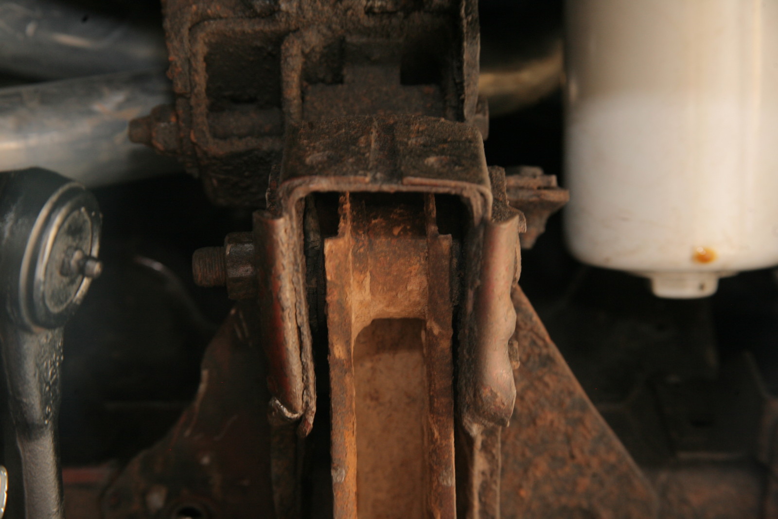
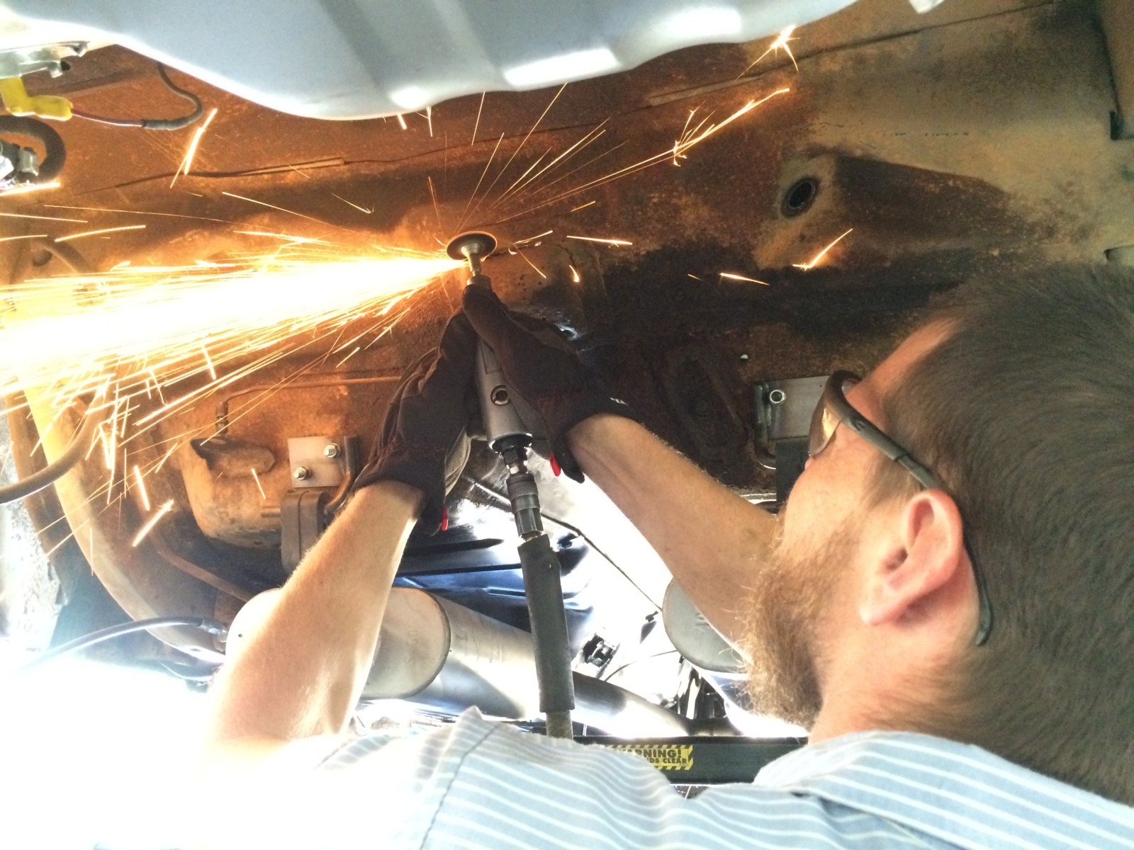
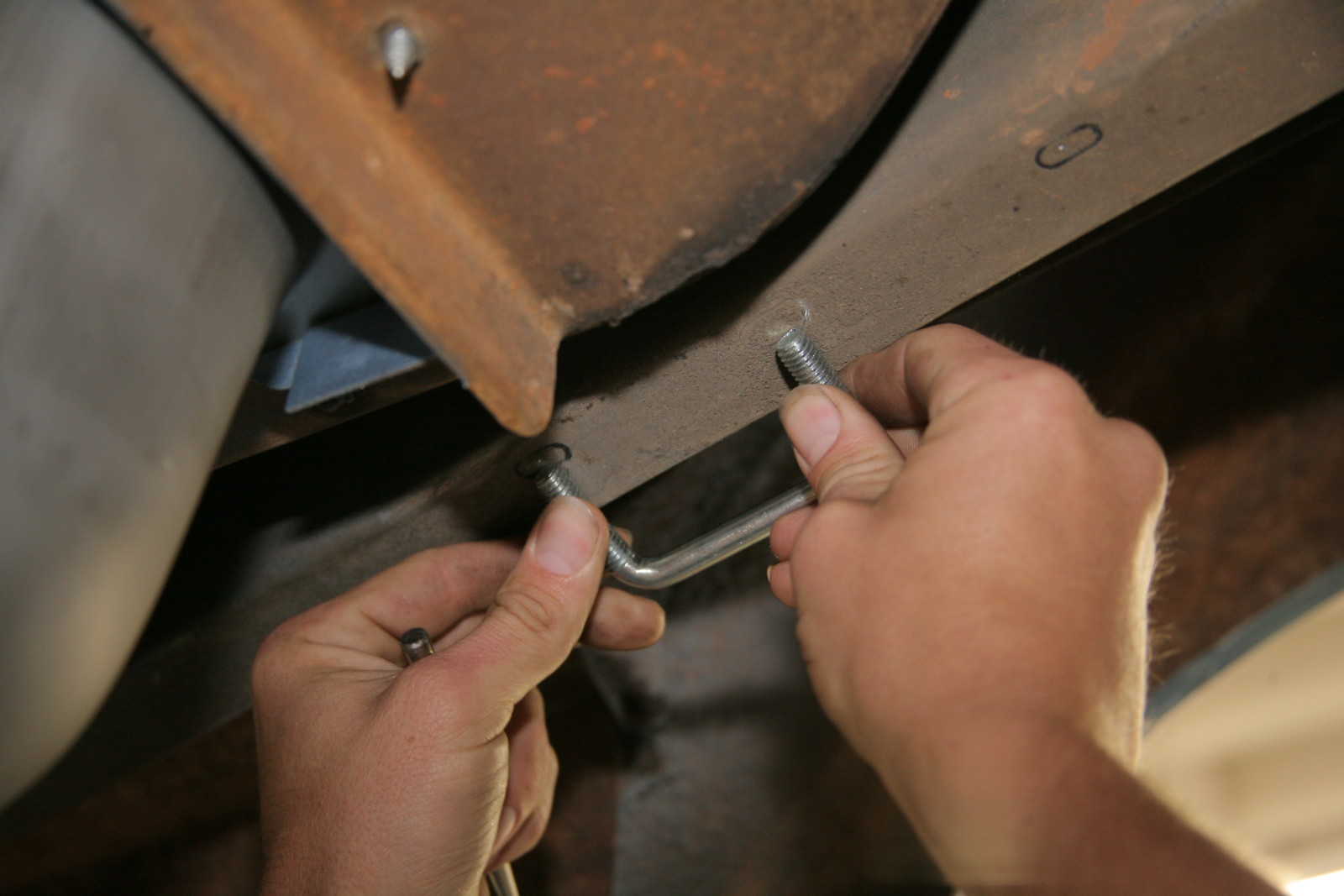
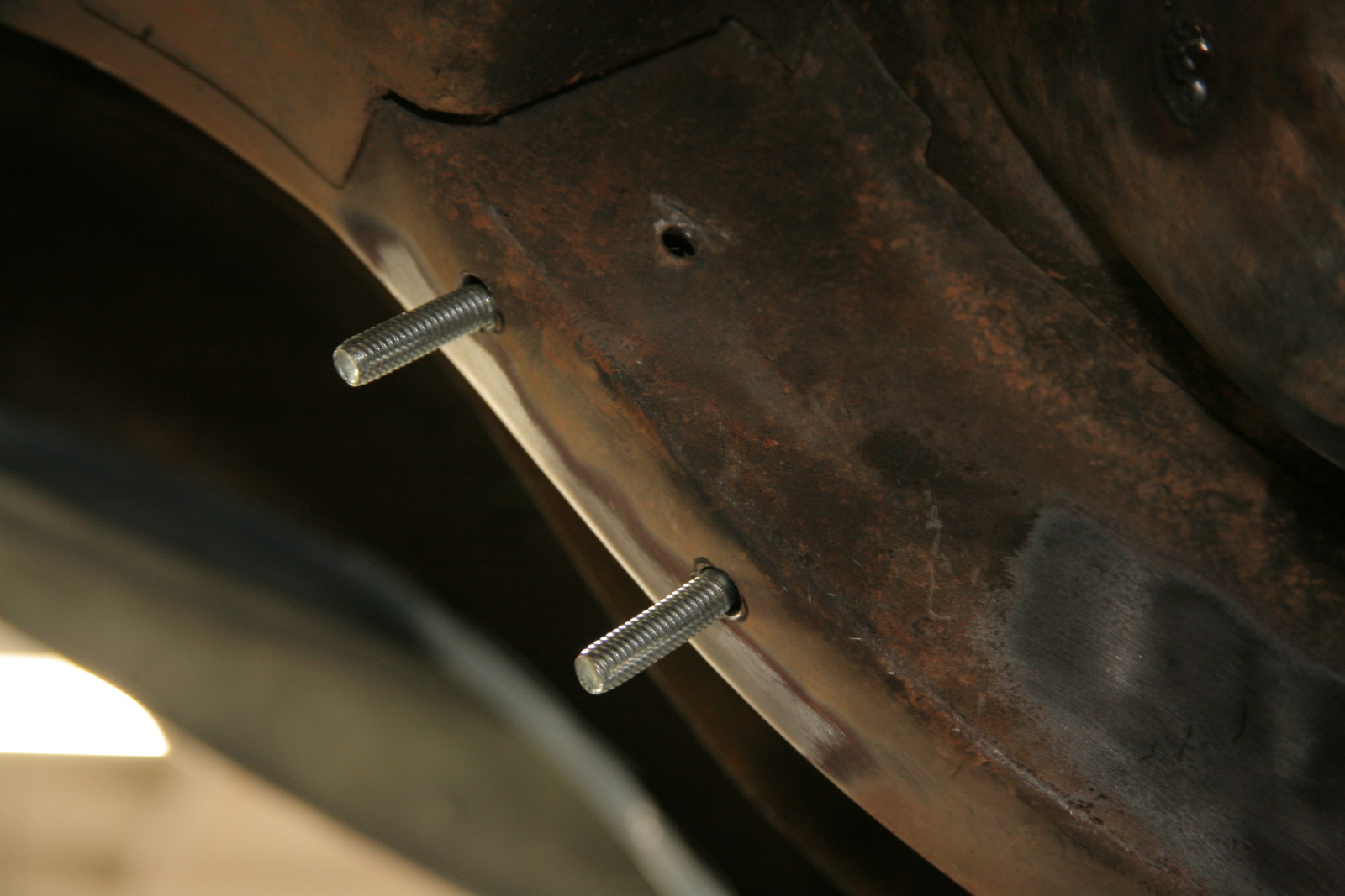
In the real world, sometimes life and unforeseen issues cause a project to get off course and backburnered for a bit. It’s probably happened to you, and it happened to us with our ’68 Mustang build. One of the biggest hold-ups was the necessity of replacing the framerail and lower core support on the passenger side forward of the front tire. Battery acid had literally eaten a hold straight down through to the ground and left that whole corner a rusty mess. Luckily it was non-structural and easy to isolate, but the problem was finding a shop we trusted, and of course paying for the work. It all worked out in the end and now we’re back on track and ready to make progress again. Next up; suspension.
If you remember our last installment when we swapped in a T5 5-speed trans in place of the C4 automatic using Summit Racing’s new swap kit, one of the main reasons for doing so was the joy of driving. Well, by far the biggest impact on the driving experience comes from the choice and condition of the suspension under the car, and our Mustang’s was stock and sloppy. Most of it was original and high mileage, and even the few replaced bits were essentially shot. It was drivable, but it really felt like an old, worn out car. That would never do since the owner of this particular project wants to get back out and enjoy it on the open road.
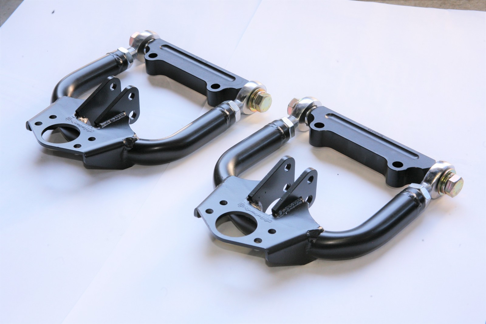
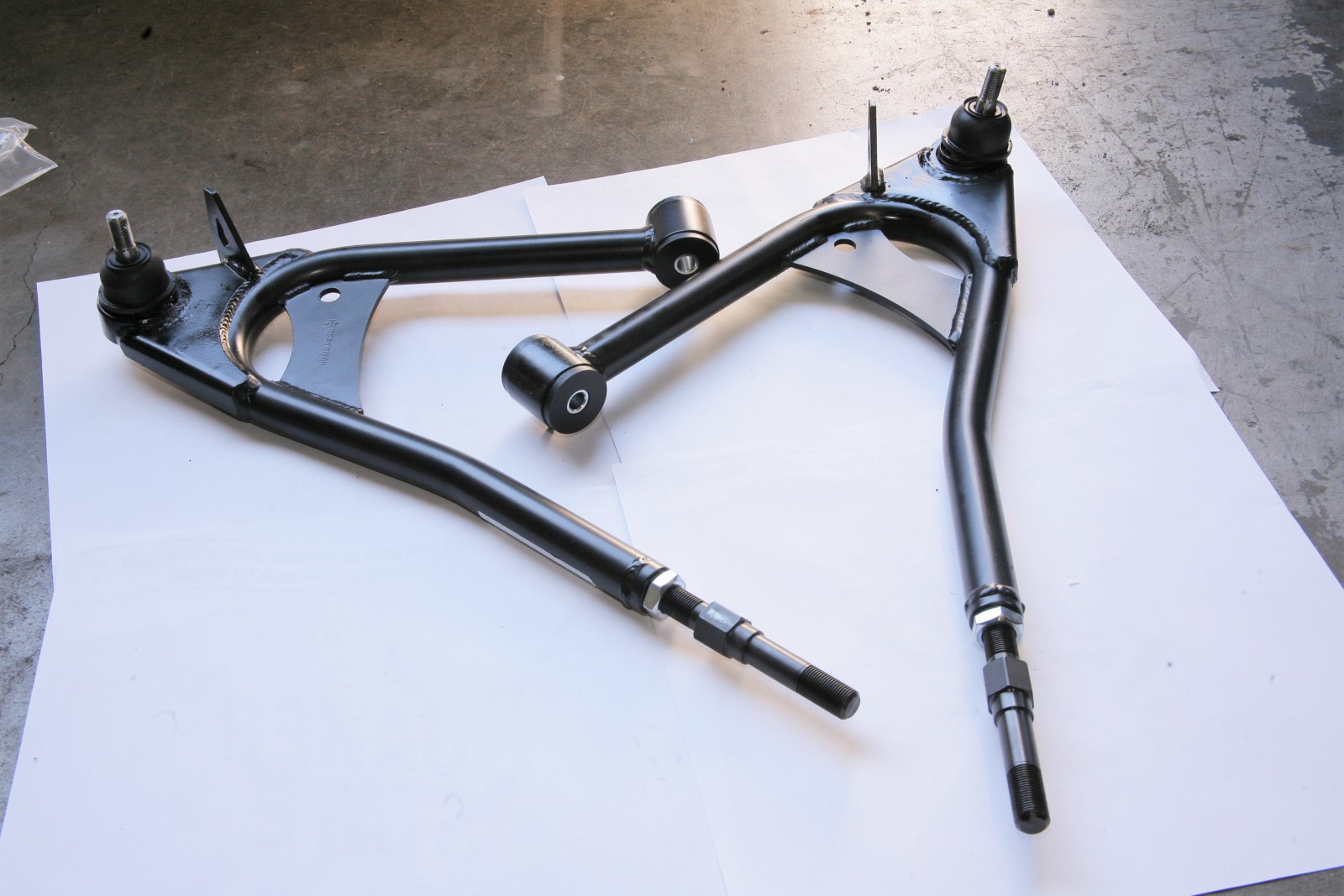
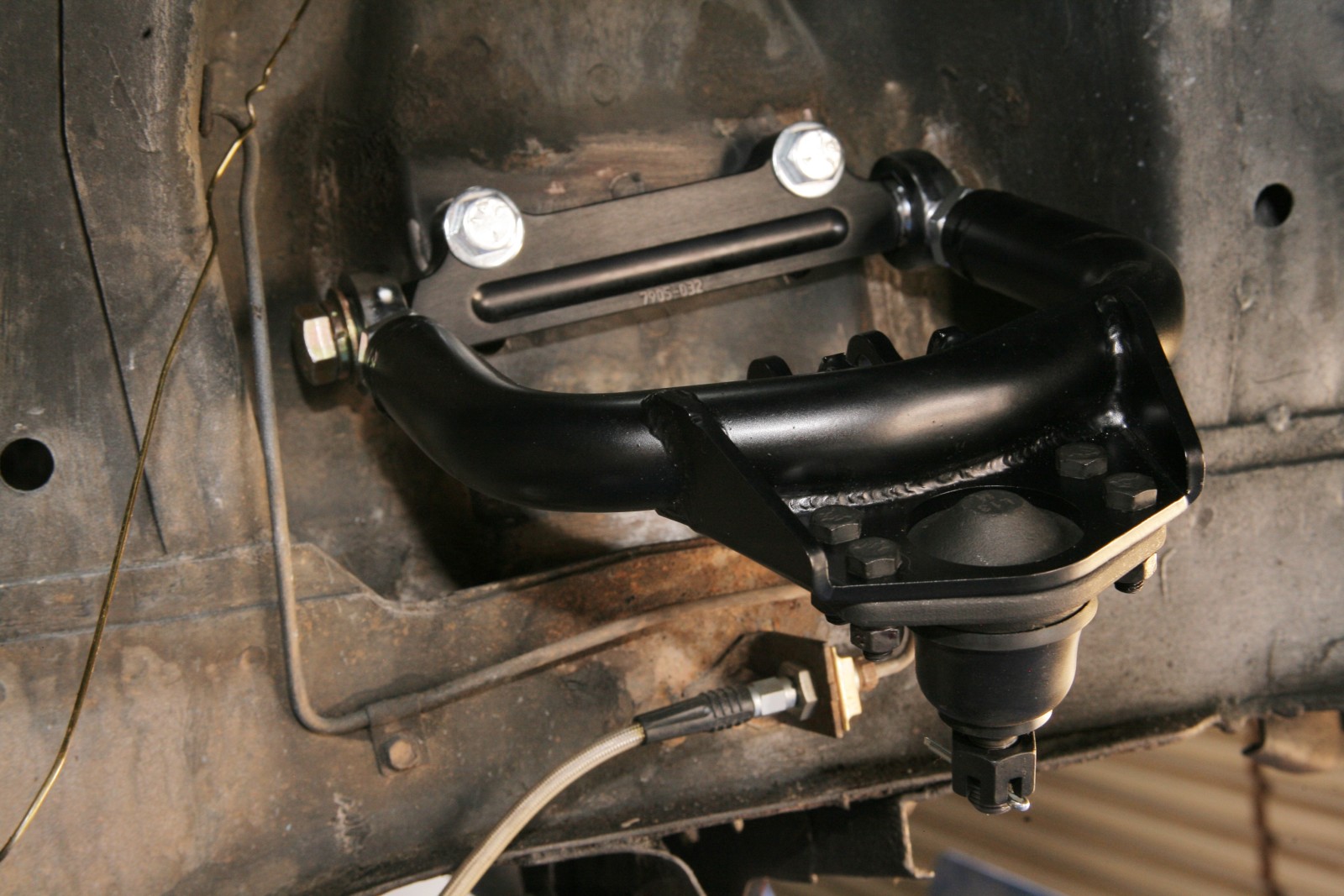
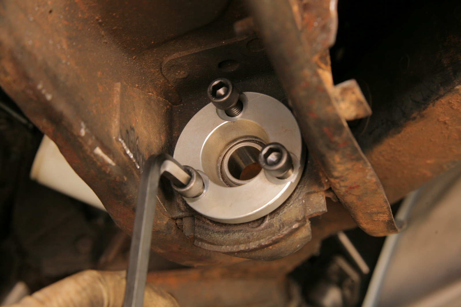
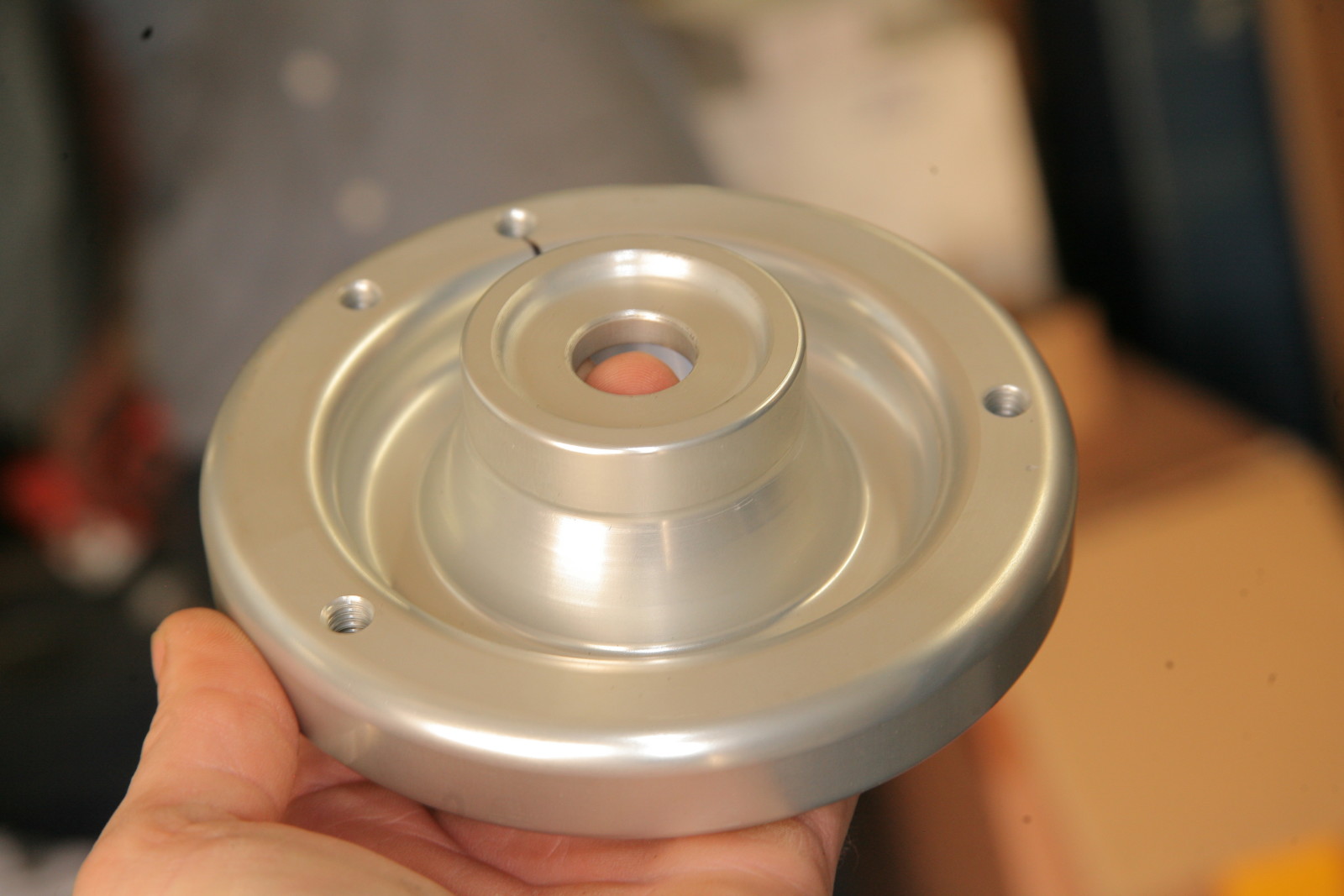
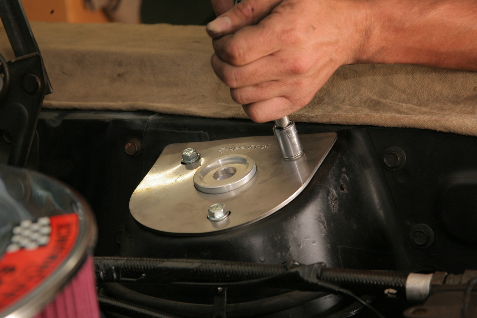
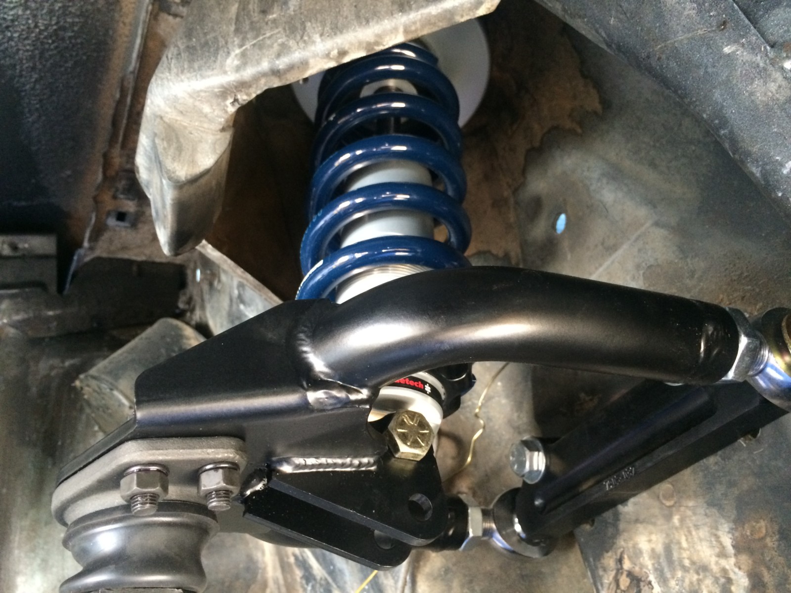
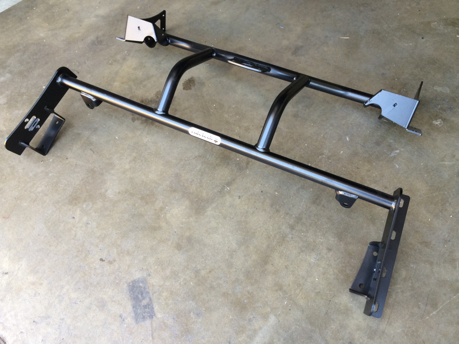
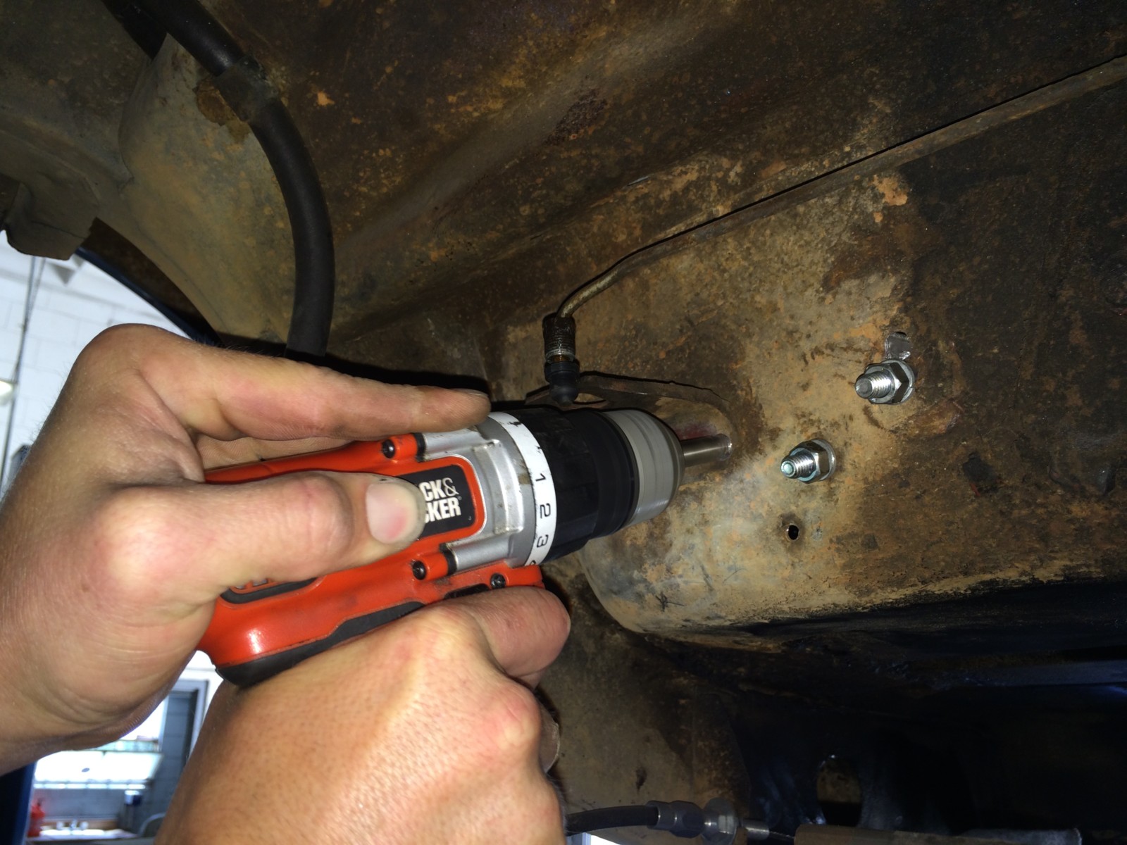
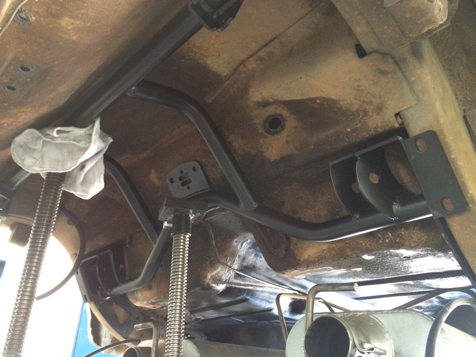
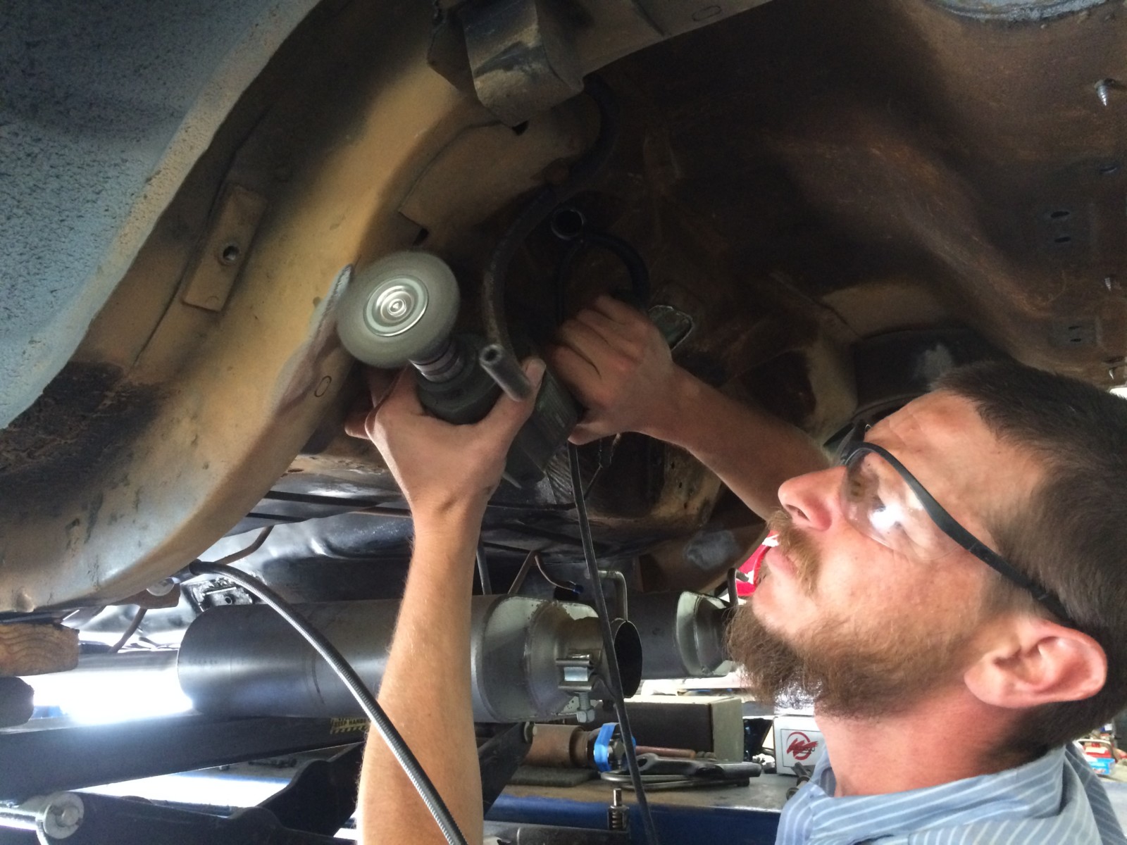
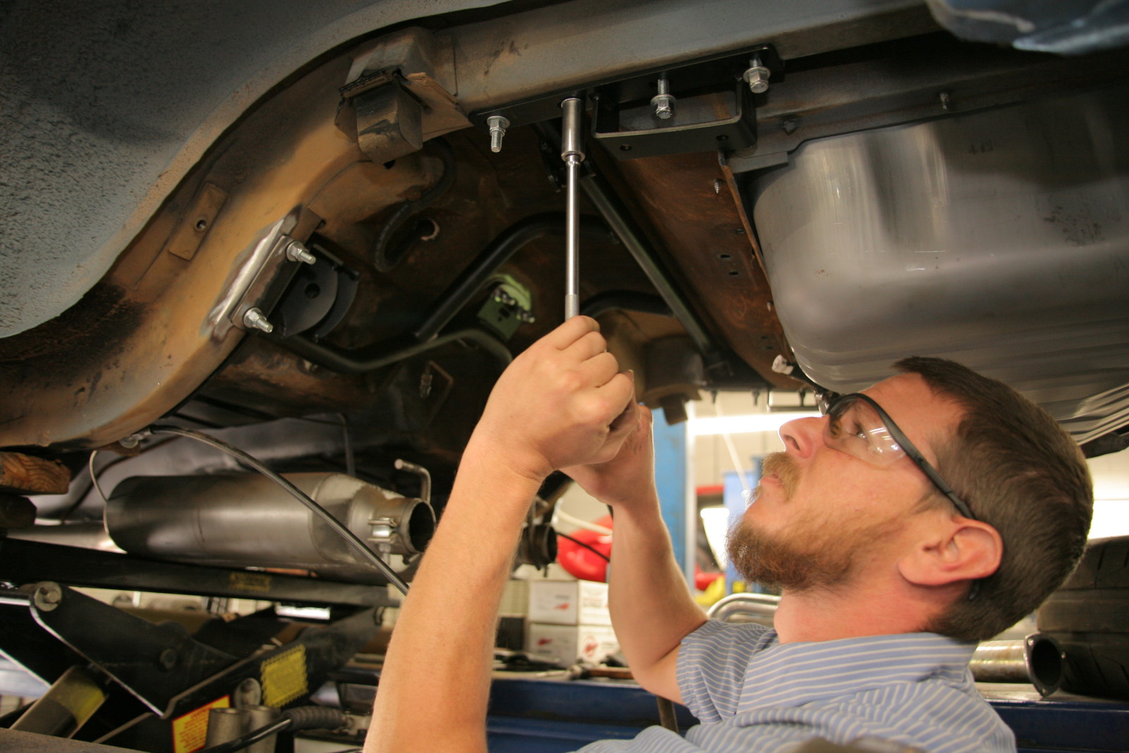
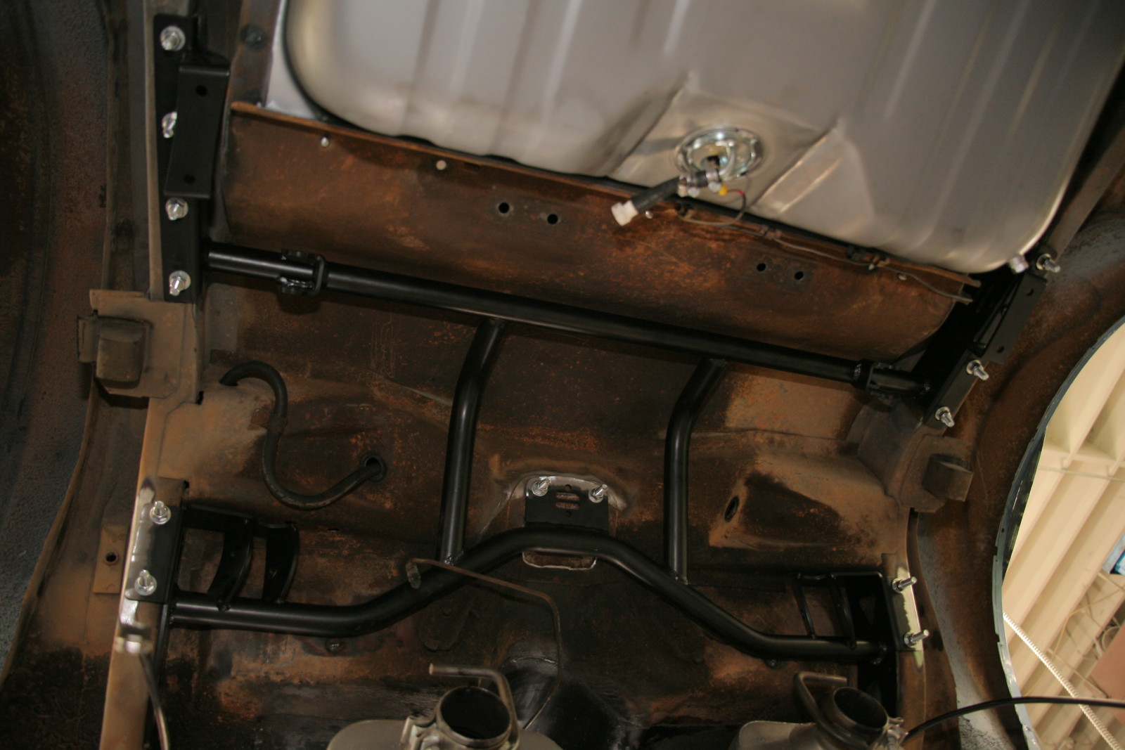
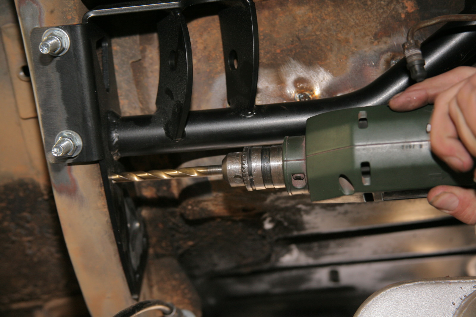
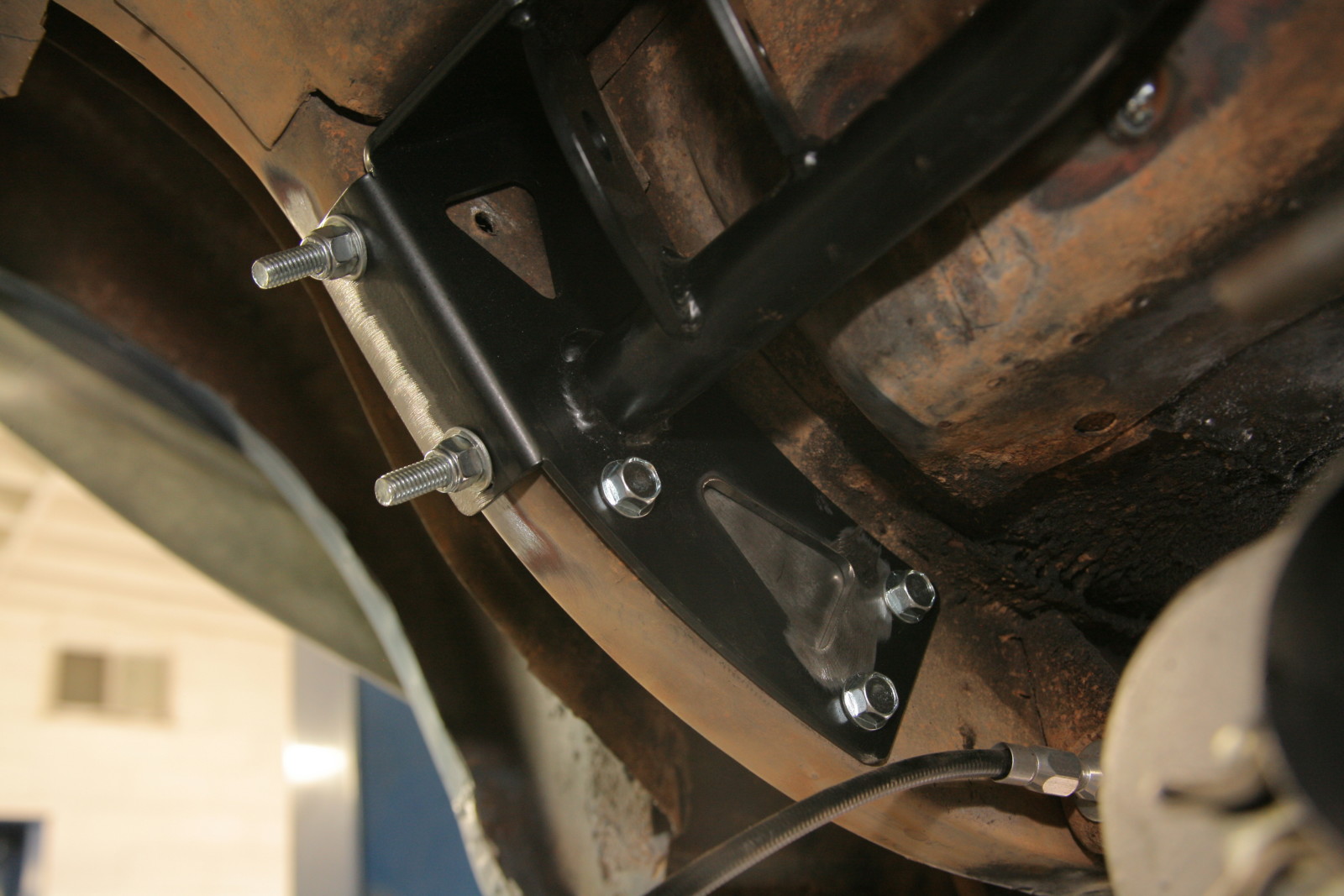
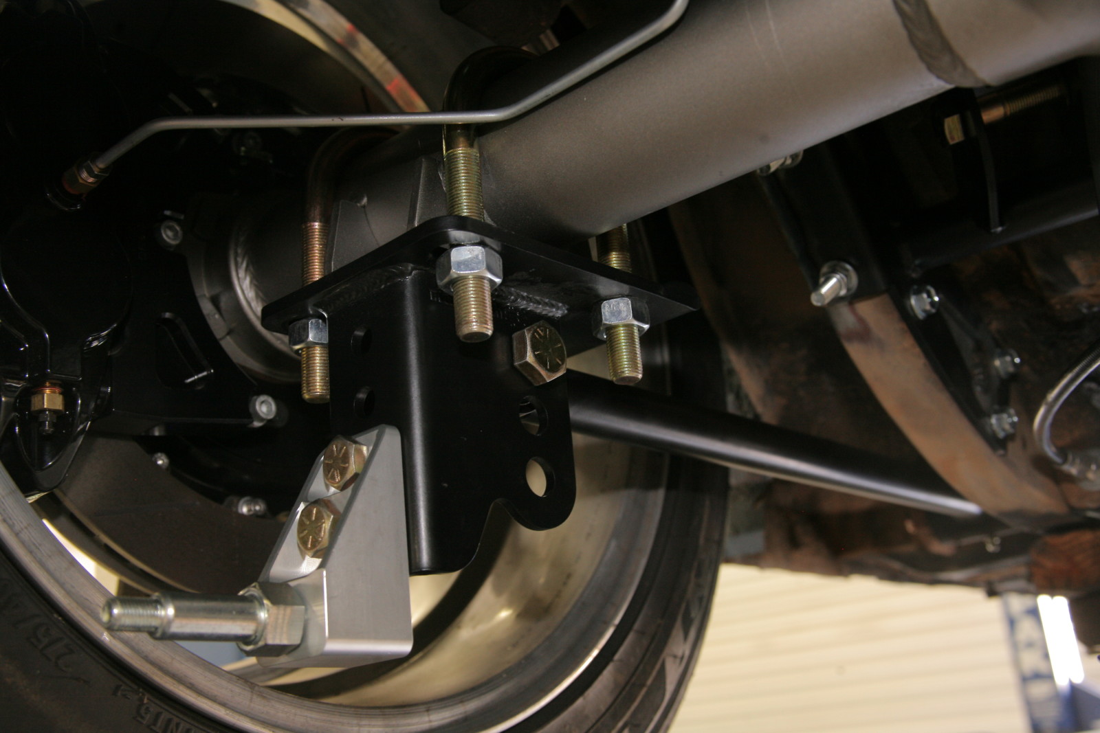
While we would like to get the Mustang up to basically modern handling standards, we also really want to keep it to a mostly bolt-in affair, so no MII style suspensions. What we wanted was something that took advantage of the good points of the suspension, but also took time to engineer out the shortcomings as much as possible. One of best solutions we found was via RideTech’s CoilOver System for ‘67-‘70 Mustangs. The system is a complete front and rear package that includes their HQ Series CoilOvers, front upper & lower tubular StrongArms, a MuscleBar anti-roll bar, and a 4-link conversion for the rear. The front is almost a complete bolt-in affair with only minimal work required. The rear is a bit more involved, and does require some welding, but after speaking with RideTech technicians and reading through the instructions, we were convinced that it was a task we could take on.
While we’re opting for the simplicity of coilovers, the systems also support RideTech’s air ride options, if you’d like the ability to tuck the tires way up in the wheel wells while at a show. For us, we just want to get the improved dynamics that RideTech engineered into the system. While it should comfortable for long distance drives, which is important since road trips and cruises are in the cards, the higher spring rates and performance valving in the RideTech shocks will also make our Mustang a much more capable performer- something which we’ll be testing down the road.
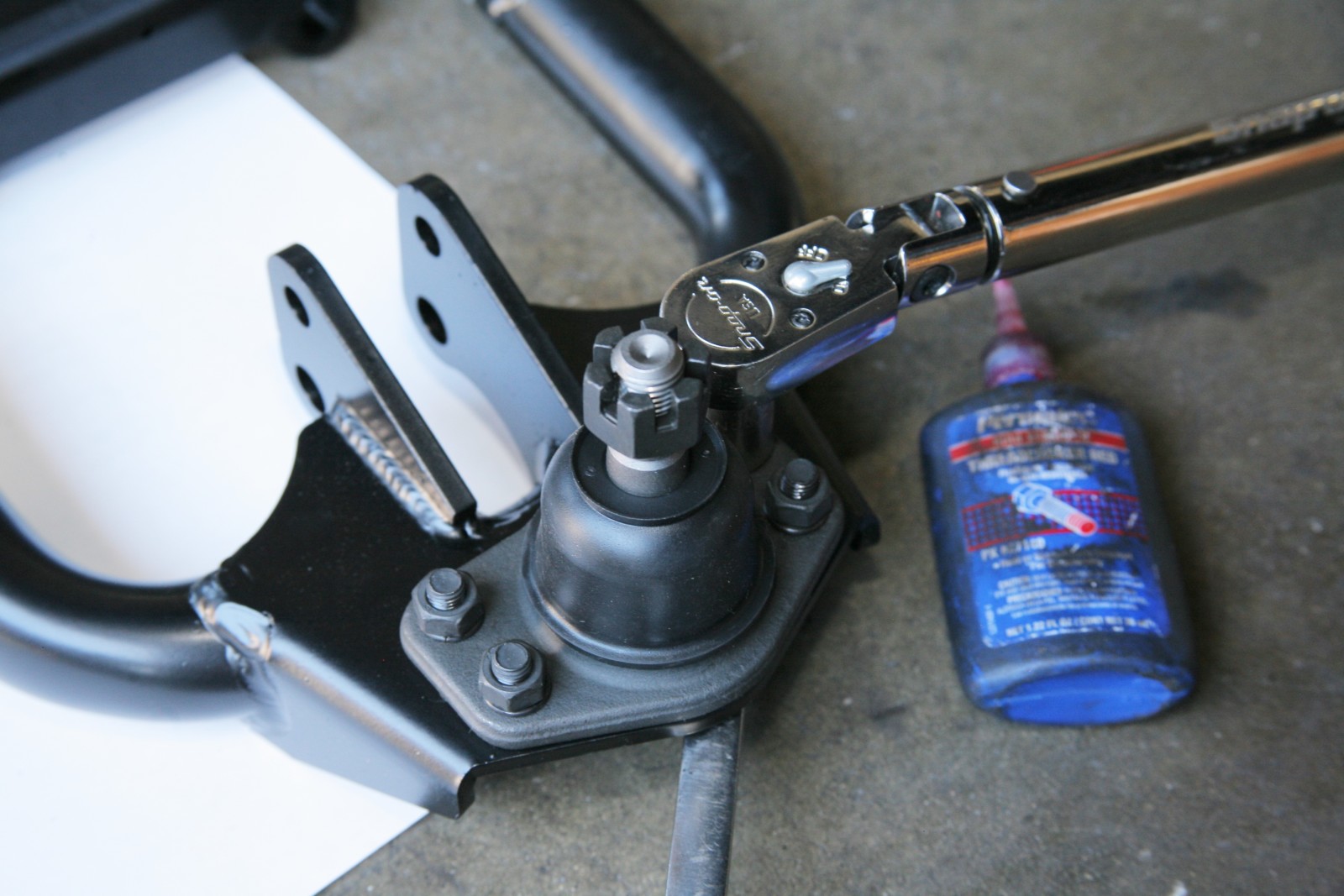
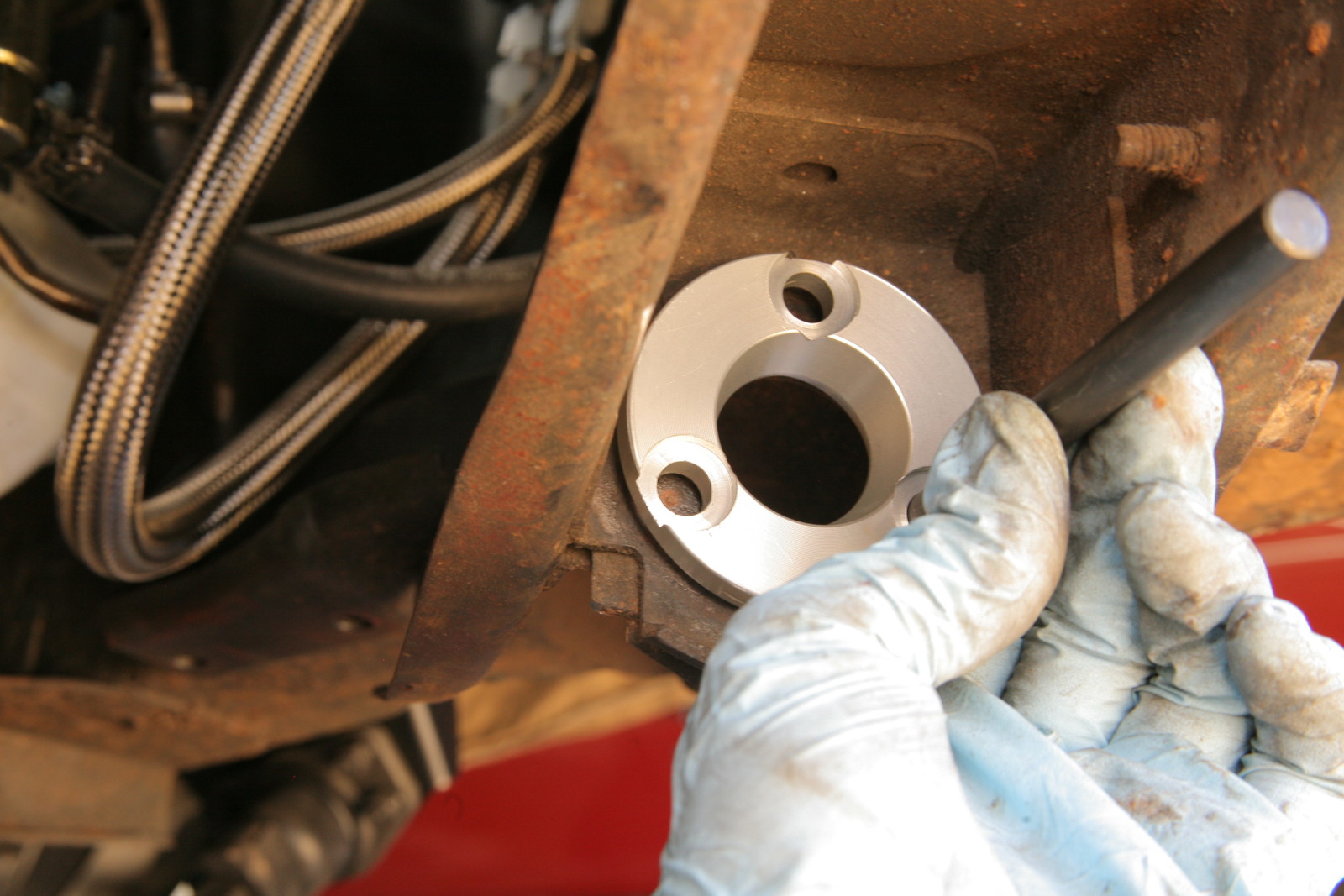
For now, we’ll show you exactly what involved with getting it installed.
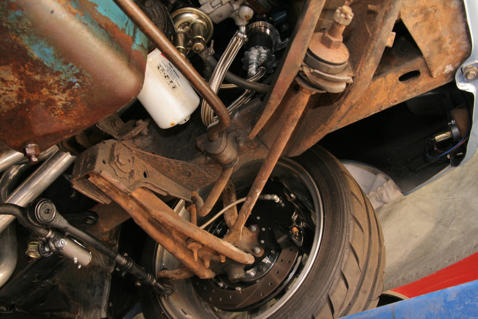

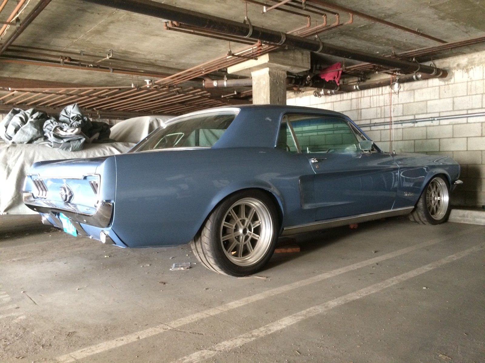


What wheels are those size type and tire please
Hi Andrew,
Apologies for the late response! These are 17×8 & 17×9.5 Vintage Wheel Works V50 with 235/40 & 275/40 Nitto NT05 tires
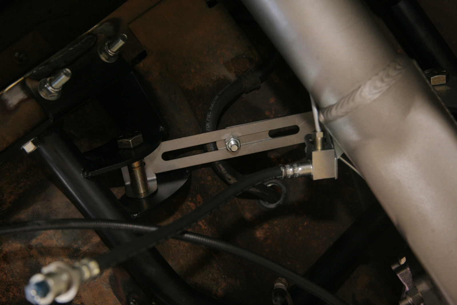
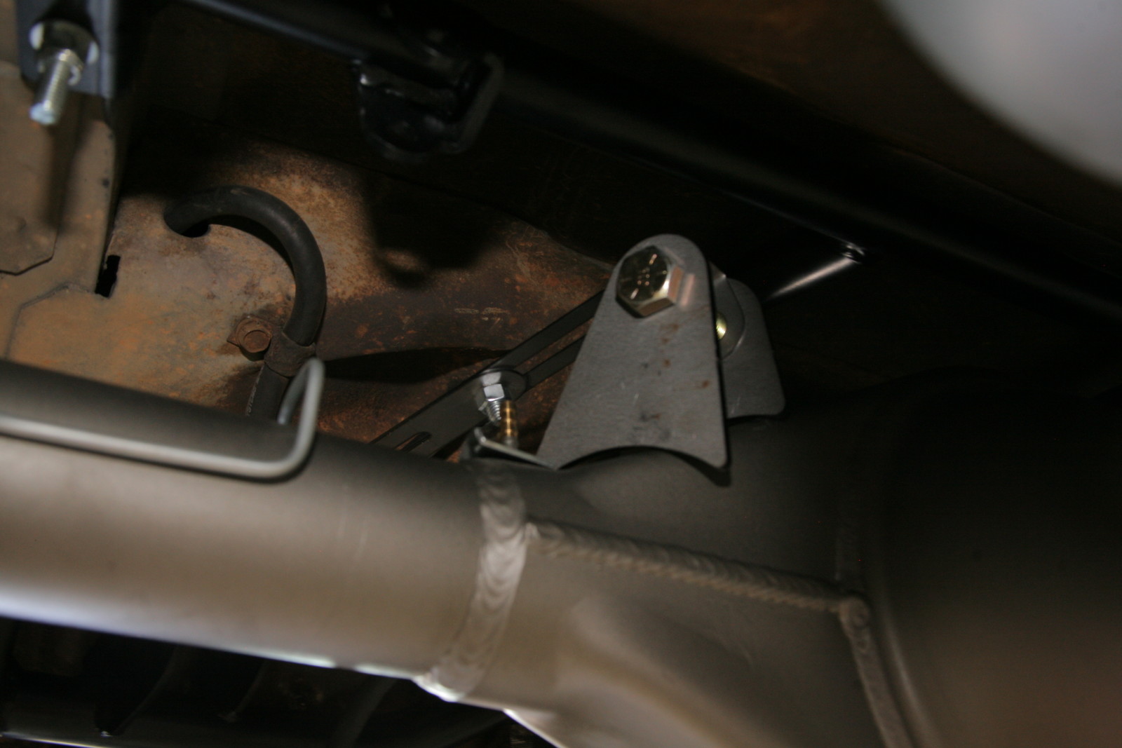
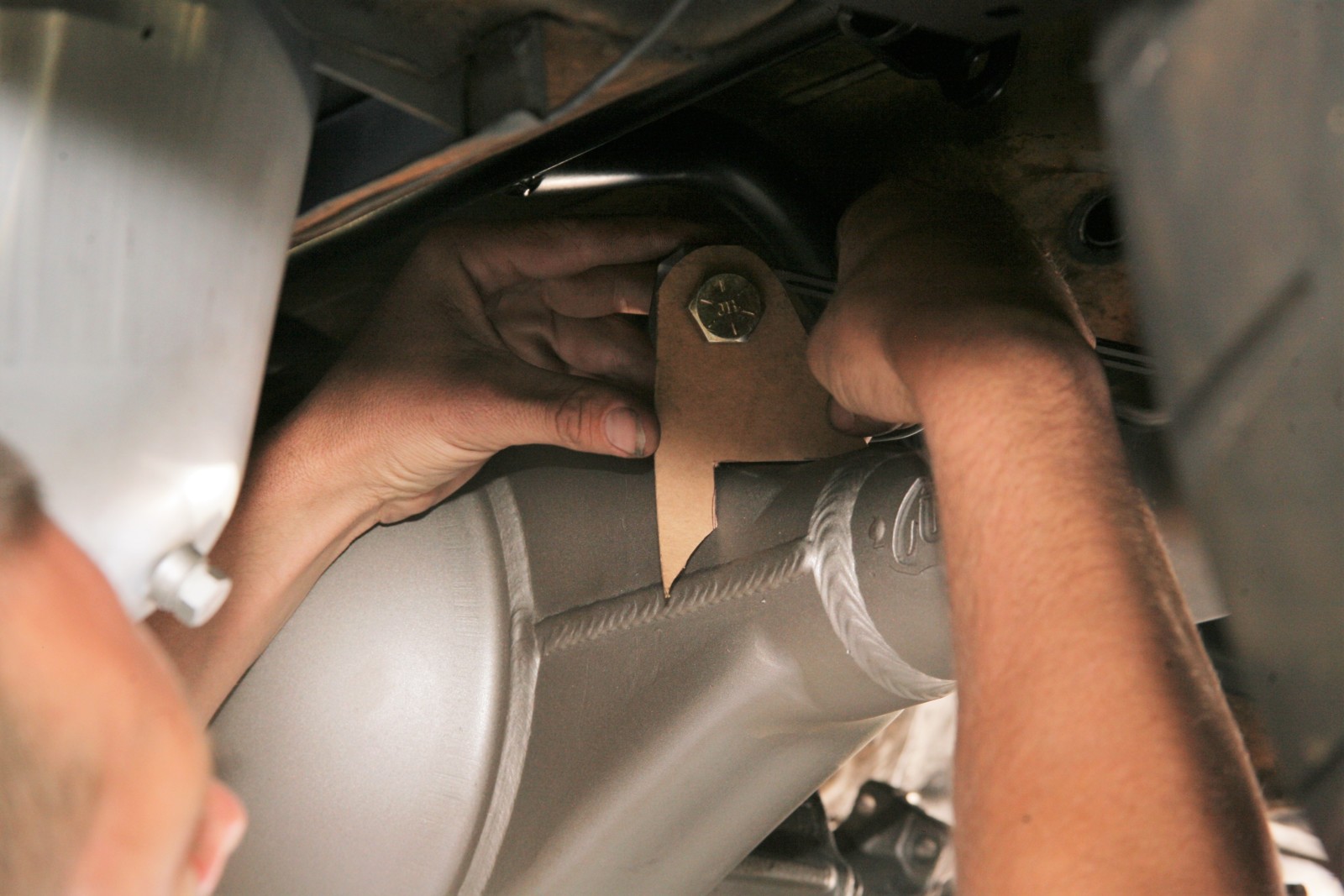
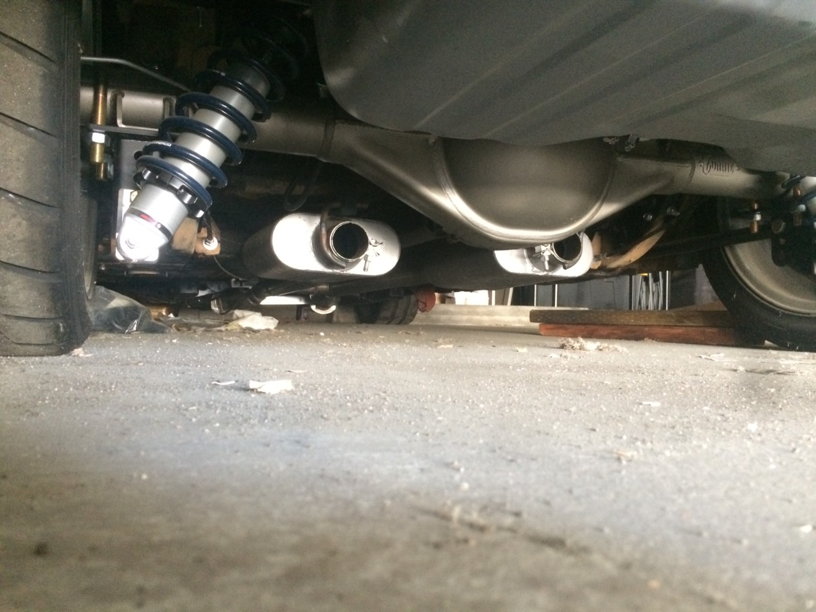
Nice article. Is it possible to show the final exhaust layout?