I was working on my engine the other day when I pulled the distributor cap and noticed what looked like grease around the inside of the cap. But what really caught my eye was the strange buildup of crud on one end of each spark plug wire terminal on the cap. What causes this and how do I prevent it?
W.D.

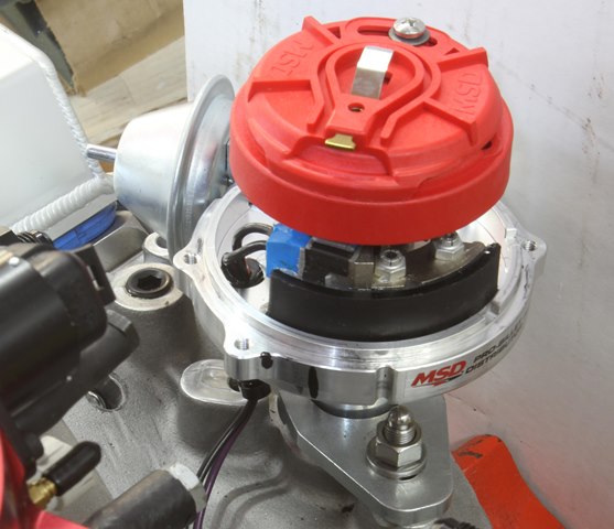
This is the photo of the cap that W.D sent us with his question. Notice the dark iron oxide area on the inside of the cap. Our guess is that the inside of his rotor was absolutely filled with this stuff. Also notice the whitish aluminum oxide deposits on the spark plug wire terminals. That’s not good. (Image/Jeff Smith)
Jeff Smith: At first glance, I thought the dark area on the cap was grease. But looking more closely, I’ve seen a dark brown material coating like this before, appearing like a very fine powder. Most often, I see this on the inside of HEI distributors, but it can be common on any distributor. This material is iron oxide and is the result of misfires inside the cap from errant sparks inside the cap looking for a convenient ground path.
Electricity will always follow the path of least resistance. If the rotor gap is too large, often the resistance from this large gap will be greater than the resistance created to jump down to the steel rotor screws and into the mechanical advance weights in the distributor. When this happens regularly, the electrical energy oxidizes the metal in the mechanical advance, turning some of the iron into iron oxide particles that collect on the inside of the cap when thrown off from the rotor.
So we need to discover why this is occurring.
Our first clue is to look closely at the spark plug terminals on the inside of the cap. Notice that they are not brass. These terminals are aluminum. This is an indication of an inexpensive distributor cap. Aluminum does not conduct electricity nearly as efficiently as brass or copper. This means there will be more resistance in the high tension circuit to the spark plugs. You may not realize it, but aluminum does corrode. It just doesn’t rust like iron components. But this corrosion shows up as aluminum oxide. I believe that’s what we see as buildup on the edge of each terminal. This corrosion creates resistance, which reduces the voltage that ends up reaching the spark plug. Then if your plug wires also have high resistance, this really can hurt spark energy. If you lose enough spark energy, part-throttle power will suffer and the engine will seem sluggish and unresponsive to throttle.
But what’s also interesting is the fact that this corrosion is located on the leading edge of the terminal. This is a clue that the rotor is in the wrong position when the pickup aligns with the spinning pole piece and triggers the coil to fire. This is most commonly referred to as rotor phasing. MSD has a good video on what happens when the rotor is not phased properly.
In this case, the rotor is retarded in relation to the pickup. So when the pickup triggers the coil to fire, the rotor has not yet advanced enough to line up with the terminal on the cap. The deposits on your cap indicate that the rotor consistently fires short of the spark plug terminal. This requires the spark to jump the large gap between the rotor and the cap. If the rotor is retarded enough, it might actually bleed voltage off to the previous cylinder. You won’t necessarily feel this as a dedicated misfire because that voltage ends up in a cylinder that is on the exhaust stroke. So the plug might fire, but it will be doing so into essentially a dead cylinder. The real issue is that some voltage is being siphoned off to the previous cylinder in the firing order.
The fix for this malady is to first ensure the mechanical advance mechanism is fully functional. Remove the rotor and lightly lube the mechanical advance mechanism to ensure it works properly. Next, make sure that the MSD cap is properly registered with the distributor cap pin in the slot in the distributor. It’s possible that the cap was improperly registered on the distributor. Also make sure that the cap you are using is a true MSD distributor cap with brass terminals and not aluminum.
Now mount the rotor on the distributor and bump the engine around until the balancer displays roughly 15 degrees before top dead center (BTDC). This doesn’t have to be exact. Now place the cap on the distributor and carefully place a Sharpie mark on the distributor body that vertically lines up with the Number One spark plug wire terminal on the cap. Twist the rotor to maximum advance and make another, smaller mark on the distributor body. Now remove the distributor cap and evaluate how close the rotor terminal is to line up with either the large or small marks on the distributor. If the rotor is positioned between the two marks, then the rotor phasing is acceptable. The rotor should be fairly close to the mark on the distributor. If the rotor is pointed away from both marks, then you will probably have to buy an adjustable rotor from MSD (PN 8421) to correct the problem.
This is an adjustable rotor fitted to an MSD distributor. Note that we’ve positioned the rotor just before the black line on the distributor body. When the mechanical advance moves the rotor (roughly 21 degrees or 15 initial + 21 mechanical = 36 degrees BTDC), it will swing from before the terminal to after, which will be as close as we can get throughout the entire advance curve. (Image/Jeff Smith)
This adjustable rotor allows the tuner to move the tip relative to its stock location to line up the rotor with the terminal on the cap. We chose 15 degrees because that’s a typical initial timing setting. As the mechanical advance operates, it moves the rotor ahead to advance the timing. We set up one of our test small blocks and discovered that our distributor advanced the timing and moved the rotor away from the static location, creating more distance between the rotor and the cap terminal. An adjustable rotor allowed us to move the rotor so that it remained close to the spark plug terminal.
MSD’s You Tube video illustrates this dynamically with a timing light and a hole drilled into the top of the distributor cap. You can also do this if that’s easier. Our above description is the way to set up a brand new engine and distributor so that it’s all ready to go. Hope this helps.
If I bought an MSD that that was out of phase, I’ d take it back!
’97 Civic distributor suddenly problematic — The dizzie cap’s ventilation was poor/blocked, which caused moisture retention and corrosion (that also led to the rotor becoming stuck on its shaft.) — Somebody posted that a certain truck has ventilation problem in its distributor because of a small window with mesh that gets blocked by debris over time. Somebody else said that removing water and corrosion inside his civic’s dizzie cap was becoming a weekly necessity. I realized that the dizzie cap I bought a few years ago has stopped ventilating properly. It has a sort of ‘chimney’ with a very small cap on it that allows some air to pass by not seating completely. I replaced that tiny cap with a 2″ piece of plastic tube and hey presto, the car is running smoothly for a month (in a very damp winter) with no more removals of dizzie cap to clean the posts inside it. I still would like to take the whole dizzie apart some time and clean it up. Maybe in summer.
Fords had a lot of problems with moisture in distributor cap… I think it came up from inside the engine… not so much GMs…
I have a ford Electronic ignition distributor and it keeps stripping the inside of the rotor button I have put a brand new distributor in it and it still dose it
More than likely your distributor is dropping down too far and the shaft is being pushed up. Try shimming it up and that should allow it to stop doing that.
If the spark goes to the rotor screws then it will stop running. This a path to ground. If you are worried about the rotor screws, there are plastic screws available.
“Twist the rotor to maximum advance and make another, smaller mark on the distributor body. Now remove the distributor cap” how do you twist te rotor with the cap on?
Indeed. Very confusing, odd instructions.
Why would you even consider purchasing an “adjustable” component if your not willing or capable ?
Hello, Jeff Smith
You say he baught a cheap MSD Cap, that cap looked like a msd cap to me. Obviously you haven’t got a msd cap and rotor lately. THERE ALL ALUMINUM and still cost the same. I called that A-hole at MSD, he said there better with the aluminum. I said bull shit, and asked if someone else made there caps with brass terminals, said no. I guess I’ll have to get an accel dist
Actually the brass and aluminum terminals have nothing to do with current or voltage. Many years ago the GM trainer told us the aluminum terminals were for TVRS radio suppression wires and the brass terminals were for solid core wires and this is what causes the corrosion
on my 1993 chevy c1500 pick up truck 5.7 / 350 engine i have had 4 cap and rotors including msd cap and rotors with over 100 thousands gap between the cap and rotor / cut up cap to check gap /cut up distributor to check the gap / spark plug gap is to be 60 thousands / had to replace coil = for low voltage ? cannot find a cap and roter with less than 100 thousands gap i know about spark advance i have pressed apart distributor to line up reluctor and rotor for spark advance but that does not help the gap from cap and rotor
I just purchased a clear cap HEI unit from amazon, and it has the same thing. Well over 0.100″ gap between the rotor and cap terminals. Im trying to determine if this is ok to run, or should i bend it closer?
If a pieces of metal gets in the rotor can it be taking out
[…] Many people reported that every time they perform some maintenance in their vehicle and when he pulled up the distributor cap he found a strange buildup of crud at the end of each spark plug wire terminal, and also corrosion on distributor cap terminals, and after researching and seeking the advice from some experts we found that these phenomena happen for some reasons. […]
condenser problems.
Condenser problems
What it you don’t have mechanical Advance. I have a 99 gmc suburban with a 7.4L and have found the same issue
I have a question not on this subject. My 70 chevelle SS has been having changing problems is 14.2 volts to high at idle with nothing on?
Ya have to ask for them, but Standard Auto’s Blue Streak line was always the best. No Aluminum here. Thicker plastic. Exact fit replacements – even exact fit spark wires. No big bucks either. Moderately upscale price but very effective. Blue Streak.
Hi,
I have a 2002 GMC Savana 1500 with a 5.7ltr engine. In the last 6 months, I’ve replaced the distributor cap and rotor 3 times for a misfire problem that developes shortly after replacing the cap and rotor. When I say shortly I mean in a couple of weeks. The last time I replaced the cap and rotor because the motor wouldn’t run at all. Now I have misfires again on cyls 234567, mostly on 2 and 3. What causes this? I hope you can answer this question. Thanks,
Michael C. Pepper
Hi Michael,
I been having the same issues with my 99 Suburban 5.7. Runs good cold but has slight misfire but after warming up it falls on its face and shows those cylinders misfiring. after a few thousand dollars with multiple parts thrown at it I may have found the issue today. What I see in the dist rotor is not sparking at dead center of the post in the cap but to the left of it. This is a locked dist but I may need to go back to the adjustable so I can advance/retard the cap to spark at the center of post and not before it. Reason why I am thinking this is because I have replaced cap and rotor several times in the last few months, Spider injector, Cats, Plugs, Wires, all 4 02 sensors, fuel pump and filter, and tested the intake gaskets. I have had it at 2 gm shops and they could not find the issue either. I would look at the old caps and see if you have any green corrosion and see where the bald spot is on your post. Hopefully this will give you an idea.
also to add all parts are new AC Delco
I have a 2007 Silverado and am experiencing the same thing. Check engine light, misfiring, and repeated replacements of distributor cap and button, going bad after just a few weeks after taking it out of the shop (three different shops).
It’s going bad again and repeatedly spending several hundred dollars every couple of months on this is not doable for me. I’m just searching. Hoping I can find something to show my mechanic.
Hi, what would cause my distributor cap to not provide spark to two cylinders? 69 chevy 350 with electronic ignition conversion. Have replaced cap and rotor several times still no spark from cap to same two cylinders
Thanks so much for the information and i’m really blessed.
Here is a quote from the article by the expert, Jeff….. “Aluminum does not conduct electricity nearly as efficiently as brass or copper.” You’d think he could look up a table of electrical conductivity of metals before assuming that. True statement for copper. When is the last time you saw a distributor cap with copper terminals? You haven’t in the last 50 years. You will find aluminum and brass terminals. And aluminum has about double the electrical conductivity of brass. So much for “experts.” I think caps with brass terminals were made with brass to give it longer durability than aluminum. But as cheap as caps are, why not use the one with DOUBLE the elecrtrical canductivity?
Thanks for the info! I was stumped as to why I had to keep changing distributor caps from gunk buildup so often. At first I attributed to cheapo parts but then even the GOOD ones were failing from buildup. This gave me new insight on the problem and offers me a new possible solution to it.
If u dont unhook brown and white strip wire from pcm the distributor want advance when you get it advanced and the gaps right hook that wire back up and itll advance the timing in the pcm and it will run like it should
MSD new caps have aluminum terminals, they cheapened them out a few years ago!! No quality caps available now…
Looking at the cap in the picture, the articles says the rotor is phased advanced, well that is true if this is a Pontiac or other counter clockwise rotation distributor engine, with the cap upside down to see inside, if this were a Chevy engine, then it is RETARDED, not advanced…
Just a thought….
[…] from the ignition coil and sending it to the ignition wires and the spark plugs. Corrosion can appear on this part, causing it to fail. If so, you might find it more challenging than usual to turn the […]
Too bad the new MSD caps have aluminum terminals! I always buy the summit racing brand, they have brass terminals!!