Editor’s Note: Mike Mavrigian has been building and writing about engines almost as
long as there has been internal combustion. Mike’s shop, Birchwood Automotive, specializes in street performance and racing engines as well as vehicle restoration. As you’ll see in this article series, he includes a wealth of information on his engine builds.
In Part 1, we covered the 499 big block’s engine specs and block prep. In this episode, we’ll cover the rotating assembly, camshaft, oiling system, and other items to finish the short block. In Part 2, we showed you the short block assembly. In Part 3, Mike assembles and installs the cylinder heads, valvetrain, and external bolt-ons like the intake manifold, distributor, and water pump.


Cylinder Heads
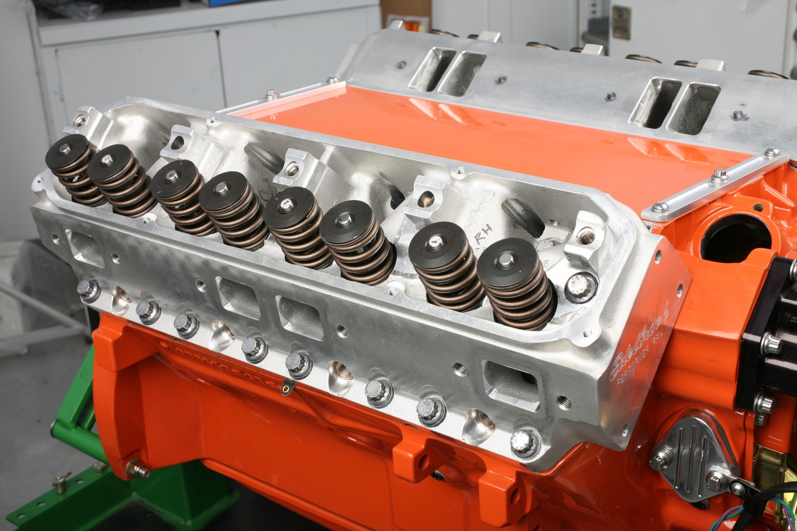
Two popular cylinder head choices for a large cubic inch big block Mopar are Edelbrock’s Performer RPM (EDL-60929) and Mopar Performance’s straight-plug aluminum heads (DCC-5153524).
Both cylinder heads come fully assembled and feature 84cc combustion chambers, 210cc intake/70cc exhaust ports, 2.140-inch intake/1.810-inch exhaust stainless valves, and 1.55-inch diameter valve springs rated to 0.600 inches of valve lift. The Edelbrock heads have angled spark plug locations while the Mopar Performance heads have straight plug locations. The Mopar heads also have an exhaust flange extended outward by 0.125-inch so exhaust header bolts won’t hit the water jackets. That eliminates a source of coolant leaks.
I test-fit both heads and decided to go with the Edelbrock heads for final assembly and the dyno run. Combustion chamber to piston clearance without the Cometic MLS (multi-layer steel) gasket in place was measured at 0.035-inch at the upper quench area. Factoring in the head gasket thickness of 0.040 inches, final clearance is 0.075-inch. Valve to piston clearance without the head gasket measured a healthy 0.250-inch intake and 0.270-inch exhaust. Head gaskets with stainless steel fire rings should not be used with aluminum heads. The hard rings won’t crush sufficiently and can dig into the soft aluminum.
I used ARP’s 12-point polished stainless steel head bolts. I applied ARP Ultra Torque Fastener Lubricant to all bolt threads, each side of the flat washers, and the underside of each bolt head. When installing washers, note that one side features a slight chamfer. This chamfered side must face the underside of the bolt head.
The bolts were tightened following Edelbrock’s sequence. I used my preferred four-step torquing process starting at 25 ft.-lbs followed by 40 ft.-lbs, 55 ft-.lbs, and a final 70 ft.-lbs.
Measuring Pushrod Length
I used an adjustable checking pushrod to measure pushrod length. I rotated the cam so the lobes were set on their base circles, and set the rocker arm adjusters with a 0.370-inch gap between the bottom of the rocker arm and the adjuster ball. I then added 0.050 inches of preload to account for the hydraulic lifters.
After installing and setting the checking pushrod, I removed it and placed a 5/16-inch ball in the pushrod cup to measure overall length. I then subtracted the ball tip diameter (0.312-inch) to get our final pushrod length. I use this method because it is difficult to accurately measure from the base of the pushrod cup. In our application, the overall length of our checking pushrod with the ball measured 8.590-inch. Subtracting the ball diameter gave me the final pushrod length of 8.318-inch.
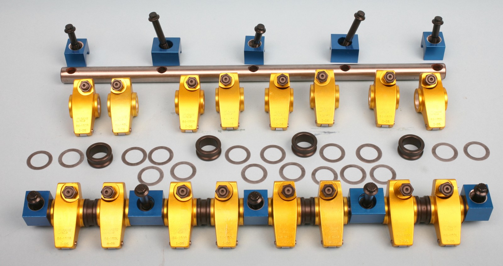
Rocker Arm Assembly
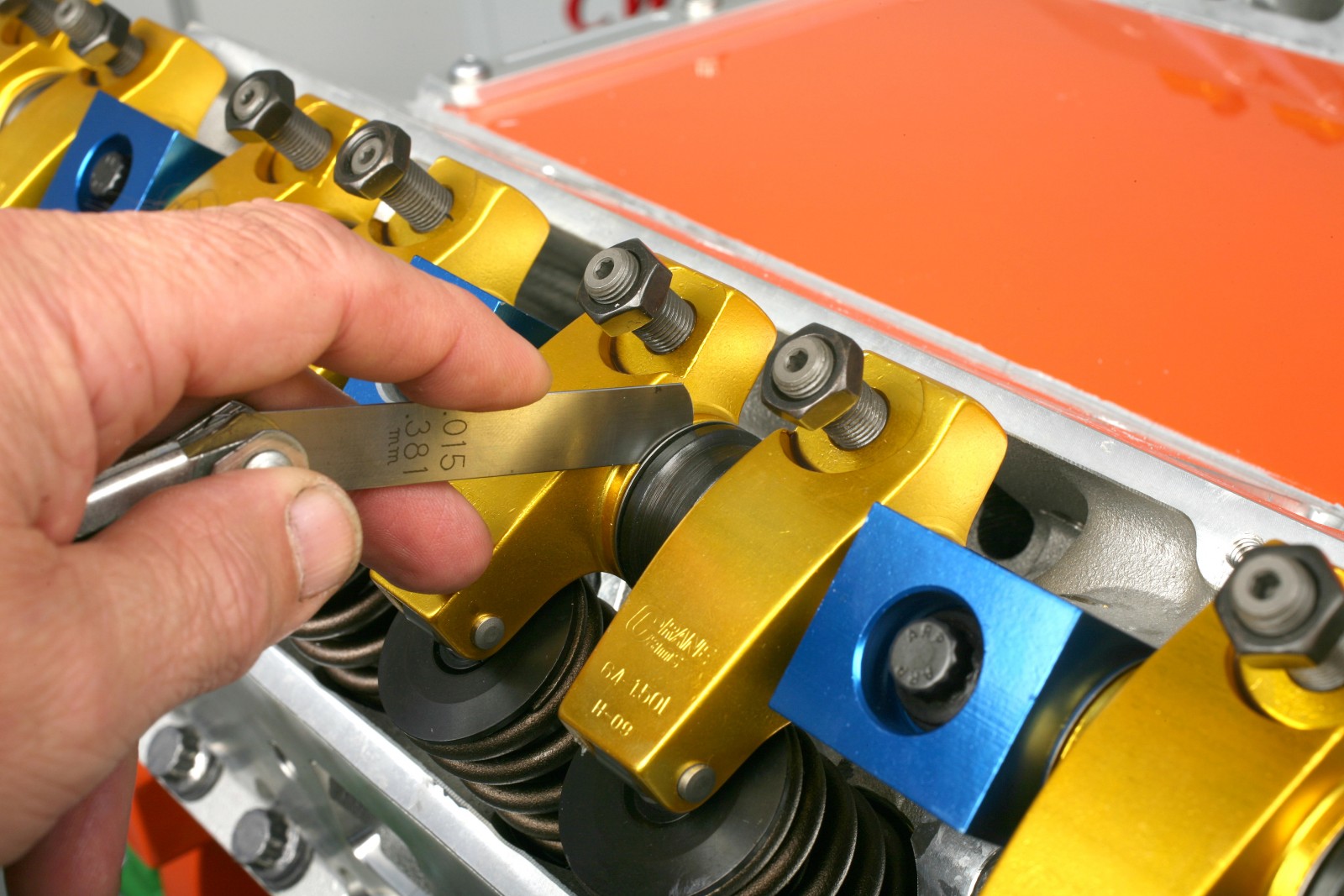
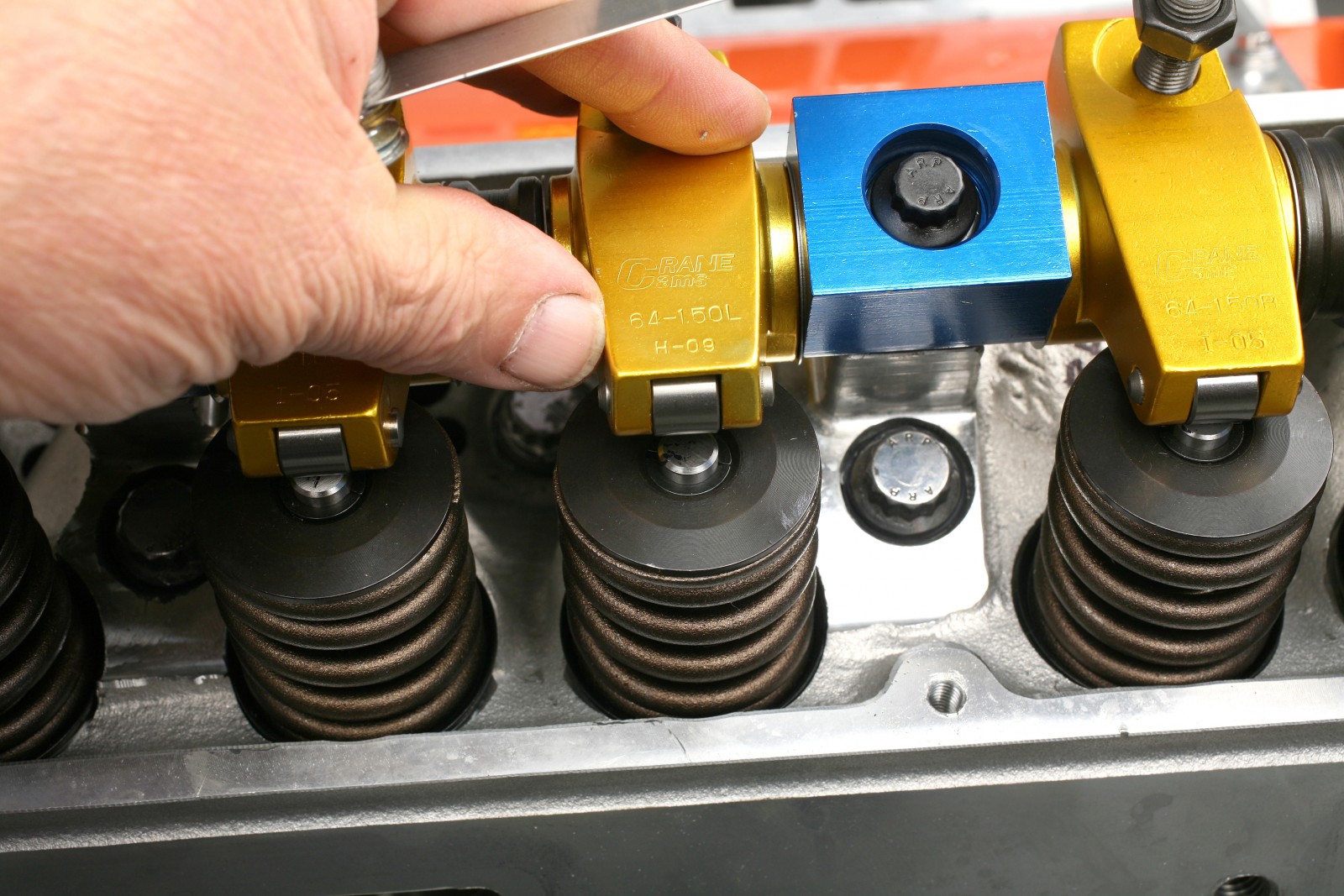
Big block Mopars use a shaft-mounted rocker system. For this build I chose Crane aluminum roller rockers in the factory 1.5:1 ratio. These rockers feature a beefy body, heavy duty roller bearing trunions, a cutaway relief on the underside of the valve area to accommodate larger diameter spring retainers, and offset threaded adjuster holes to properly align the pushrods with the rockers. Hardened ball-tip threaded adjusters and nuts plus 0.015-inch shaft spacer shims and springs were included.
I sourced Mopar Performance rocker shafts, billet aluminum rocker shaft hold-down hardware, and a 32-pack of Crane 0.015-inch shims from Summit Racing. Instead of using OE-type springs between rockers, we’ll use billet aluminum spacers and shims to obtain precise rocker arm placement.
Setting up a shaft rocker system isn’t difficult, but can require a few hours of adjusting for side clearance due to the stack-up of initial clearances. This will require a lot of measuring, disassembly, and reassembly. The trick is to be patient and keep all pieces in order during disassembly and assembly.
Bench-assemble each shaft with rockers, rocker spacers, and shims. Put the billet hold-down blocks in place (there are five blocks per head). Patience is needed to properly position the rockers so the roller tips align with the center of each valve tip. Always place at least one shim between each rocker and each rocker spacer. Additional shims may be needed to get proper rocker-to-valve alignment.
Total side clearance between each pair of rockers should be approximately 0.015 inch. During test fitting, I had to narrow a few of the spacers located between each pair of rockers. Most required removal of 0.004- to 0.007-inch of material. Each hold-down block bolt hole has a few thousandths of wiggle room, as do the bolt holes in the shaft itself, so it’s tedious to factor in all of the tolerances when trying to set rocker side clearance.
Clearance between a rocker arm and the rocker shaft should be in the range of 0.0025-0.003 inch. Generally this clearance will be okay out of the box, but you should check it anyway during test fitting.
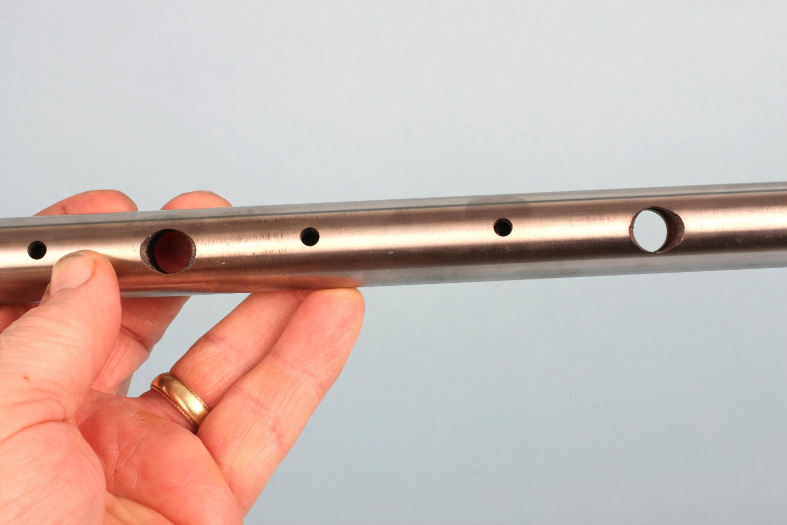
Note that one side of each rocker shaft has a series of small oiling holes. Some shafts have oil holes in-line with the bolt holes, others have offset oil holes. These oil holes must face down toward the head, biased toward the valves.
Prior to installing the rocker shaft assembly, paint each valve tip with a black marker. Then install the pushrods and loosen the rocker arm adjusters to clear the pushrod tips. Place the shaft assembly on the radius-seat stanchions on the cylinder head and hand-snug the hold-down block bolts. Thread the rocker adjusters to contact the pushrods, then inspect each valve location for rocker tip alignment. You want the rocker roller tip centered on the valve stem as close as possible. Note any locations that require alignment adjustment.
Once you’ve adjusted the rockers for valve alignment, carefully disassemble each shaft assembly and apply engine oil or assembly lube to the shaft bushing of each rocker. When installed, approximately 0.0370 inch of each rocker ball adjuster should be protruding from under each rocker arm. That means pushrod length is correct. If vertical spacing is an issue (shaft too low in relation to pushrods), radius seat spacers are available to raise the shafts.
Tighten each rocker shaft hold-down bolt to 25 ft.-lbs. (with PTFE thread sealer applied). Make sure the shafts are installed with small oil holes facing downward. You will need to check clearance between the bottom of the rocker and the valve spring retainer when the valves are closed. Clearance here needs to be at least 0.010 inch.
Once the assembly has been installed and lash adjusted, rotate the crankshaft to actuate the valvetrain. The rocker rollers wil leave contact marks on black ink you painted on the valve tips. Those marks should be no closer than 0.040 inch from the edge of the valve tips.
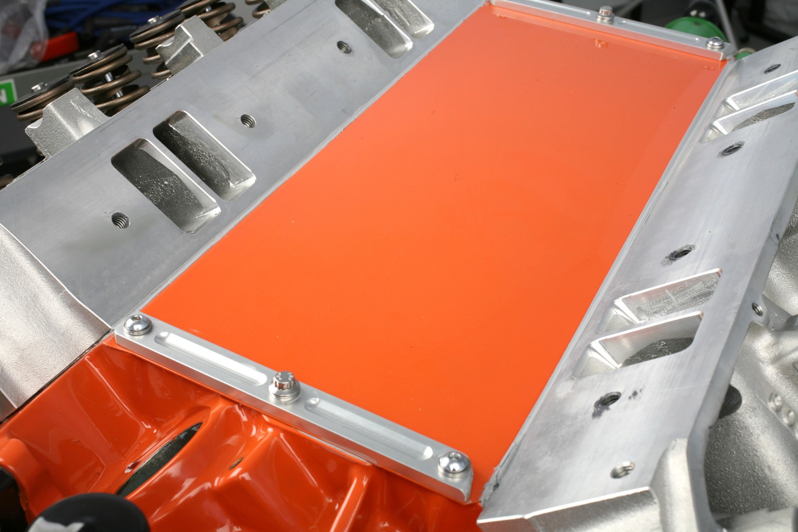
Intake Manifold
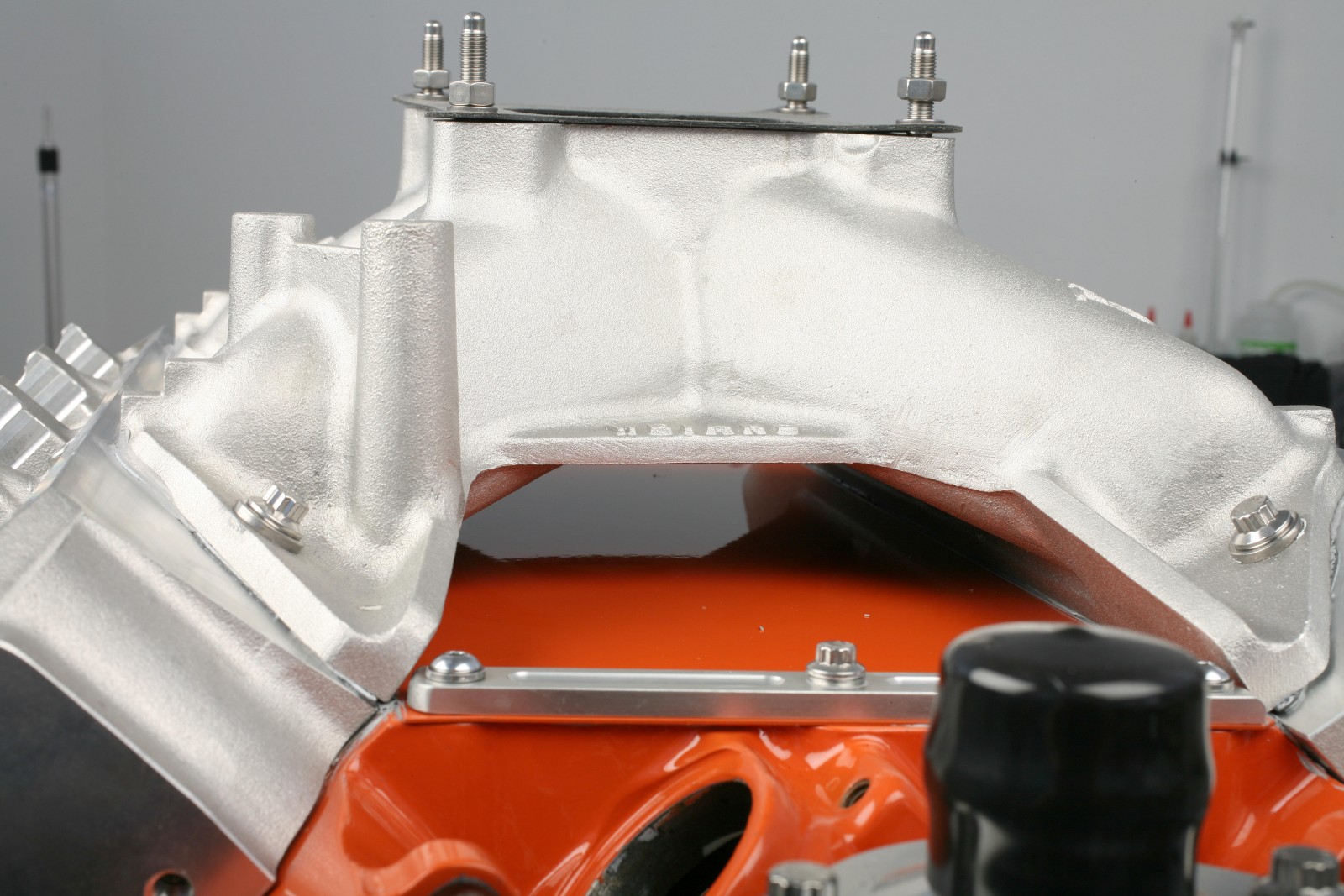
The Weiand Team G single-plane intake manifold was port-matched to the intake gaskets and cylinder heads. Only a very minor amount of material was removed from the intake manifold ports for a proper gasket match.
I opted to use an aftermarket valley cover that requires separate composite intake gaskets. I put a very thin smear of Ultra Gray RTV around each cylinder head intake port. Don’t apply a bead of RTV as this can spread out when the gasket is compressed and protrude into the intake ports, disrupting airflow.
I also applied a very light, thin smear of RTV on the gaskets to hold them in place during assembly. If you expect to remove the intake manifold regularly, you can use a thin smear of grease on each side of the gaskets as an alternative to RTV. Under compression, the grease will help seal the intake and will make it much easier to remove the manifold. Since the intake manifold bolt holes are open to oil (open to the top of the cylinder heads), I applied PTFE thread sealer to threads on the ARP intake manifold bolts.
The intake manifold is torqued in three steps: 10 ft.-lbs, 15 ft.-lbs., and a final 25 ft.-lbs. The four center manifold bolts are shrouded by the runners and plenum, so I used a 3/8-inch drive torque wrench with a two-inch wrench extension. Since an extension effectively lengthens the torque wrench, you have to reduce the torque value to compensate so you don’t overtighten the bolts. I used the extension to tighten all eight bolts to ensure equal torque values.
Determining Torque Value with an Extension
The formula for determining torque value with an extenison is L / L + E x TE = TW.
L = torque wrench length measured from the center of the grip to the center of the ratchet head
E = wrench extension length from center of square drive hole to center of the box wrench end hole
TE = desired torque value
TW = actual torque wrench setting
In our case, the torque wrench was 14 inches long and the wrench extension was two inches long. Using our formula, L divided by L plus E (14 divided by 16) equals 0.875.
Next, we multiplied 0.875 by the desired torque setting to determine the actual torque wrench setting. For our initial torque setting of 10 ft.-lbs., we multiply 0.875 x 10. The result is 8.75 ft.-lbs., which is where we set our torque wrench. We repeated the process for the remaining torque steps.
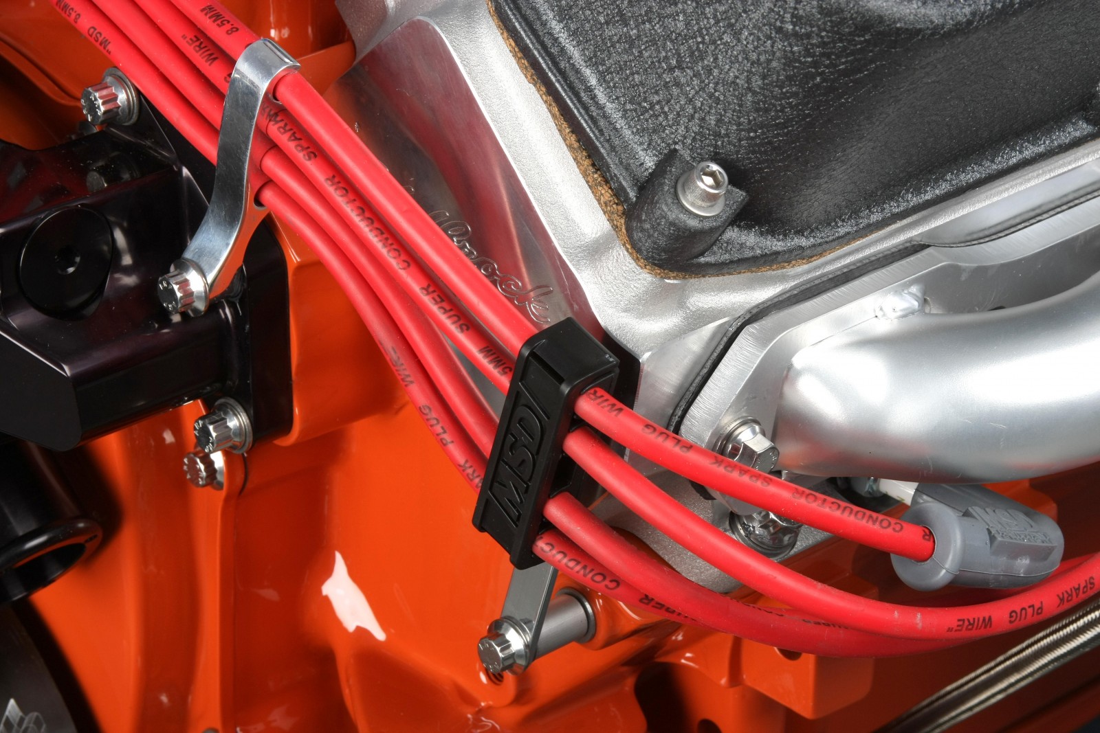
Crank Trigger and Distributor
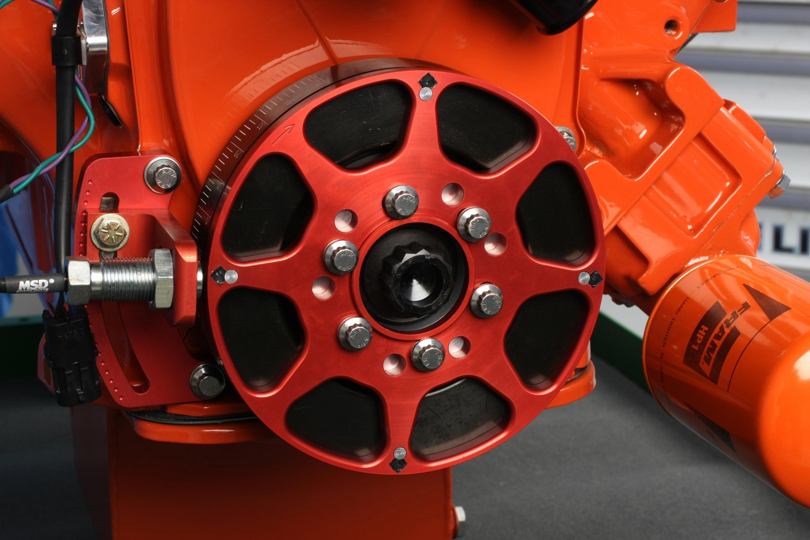
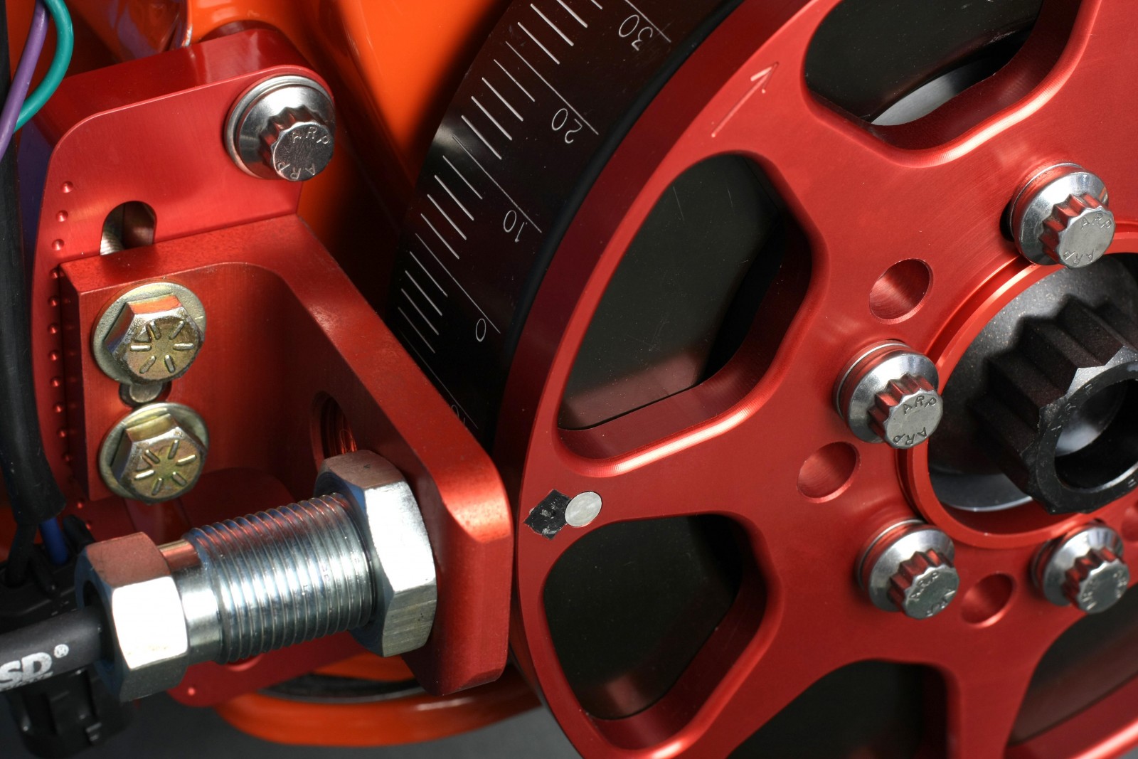
For this build, I used MSD’s crank trigger ignition system. It features a reluctor wheel mounted to the crank damper and a stationary signal pickup sensor. This allows the engine to fire based on crankshaft position instead of through the distributor. That eliminates tolerance variables, including potential slop at cam gear lash and the timing chain, that can throw off ignition timing.
With #1 cylinder at TDC, we rotated the crank to 32 degrees advance. We installed the reluctor wheel on the crank damper so that one of its magnets aligned with the pickup sensor. During the dyno run, we can make further timing adjustments if necessary.
When installing the pickup sensor in its adjustable bracket, the threaded sensor body allows you to adjust the air gap between the pickup tip and reluctor wheel magnets. An air gap of 0.050- to 0.080-inch is acceptable. We set ours at 0.065-inch.
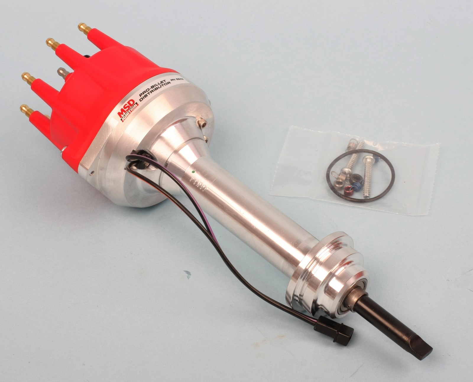
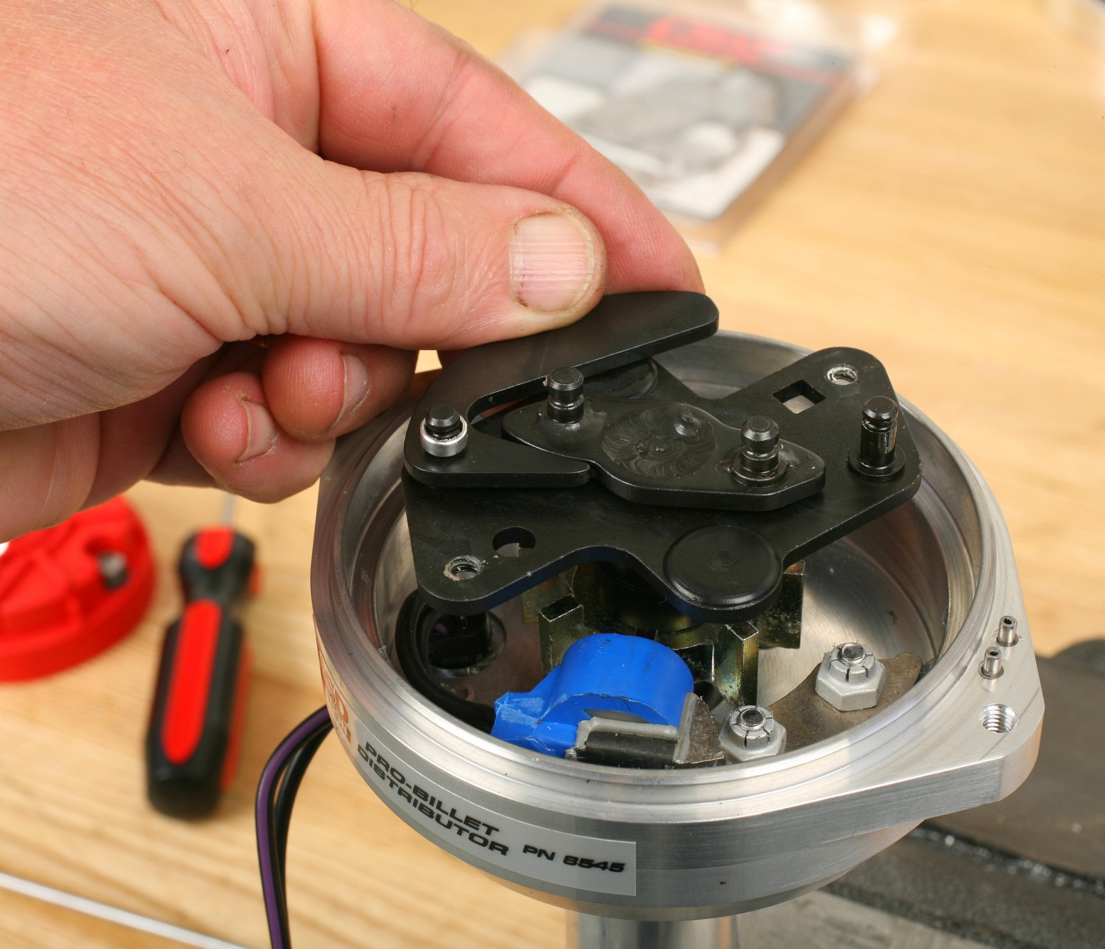
The MSD Pro Billet distributor features a centrifugal advance. Since we’re running an MSD crank trigger system, we need to lock out the centrifugal advance as follows:
- Remove the springs, weights and the advance stop bushing from the advance assembly. You’ll need an 11/32-inch open-end wrench to remove the stop bushing’s lock nut. Be careful not to lose the small flat washer that’s under the locknut
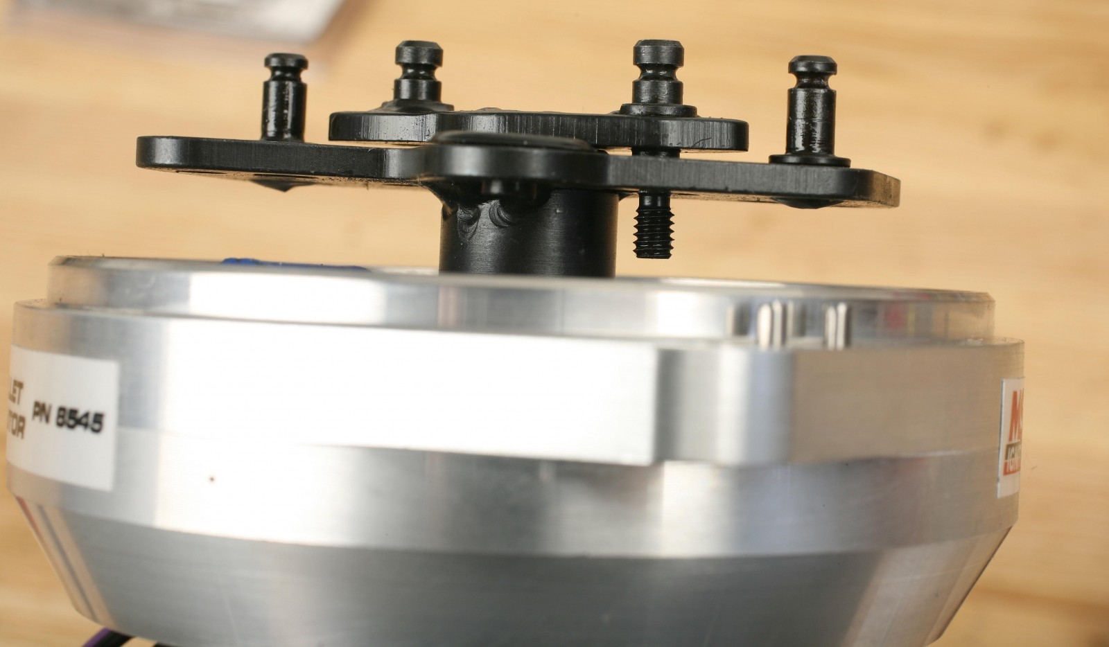
- Remove the roll pin from the shaft collar and slide the shaft out of the housing about two inches
- Rotate the shaft 180 degrees and insert the advance stop bushing pin into the small hole in the advance plate
- Install the washer and lock nut on the advance stop bushing. This locks the advance in place
- Slide the shaft into the collar and install the roll pin
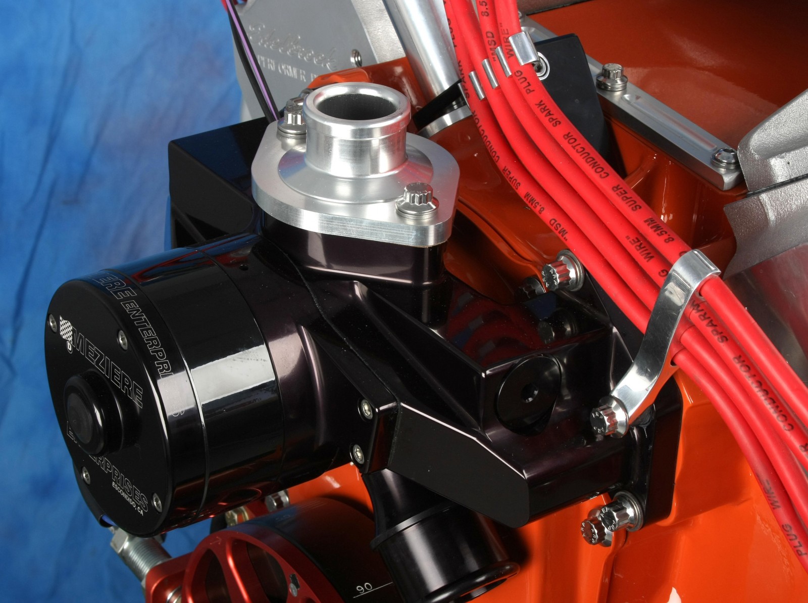
Water Pump
Using an electric water pump offers two primary advantages. It eliminates parasitic drag by doing away with a drive belt, and provides reliable water flow that isn’t dependent on crankshaft rotation.
I opted for a Meziere electric water pump. The CNC-machined billet aluminum pump features a stainless steel main shaft and ceramic seal, and weighs a mere 7.1 lbs. It fits Mopar B and RB big block engines as well as HEMIs. The pump is rated to flow at 35 gallons per minute, suitable for engines making up to 650 horsepower. A wiring harness with a 20-amp fuse is included.
The pump mounts to the front of the block with six stainless steel socket head cap screws and AN washers. Gaskets are provided with the pump. I applied a light bead of Ultra-Black Permatex RTV to each side of both gaskets prior to installation. The water pump mounting bolts were torqued to 25 ft.-lbs.
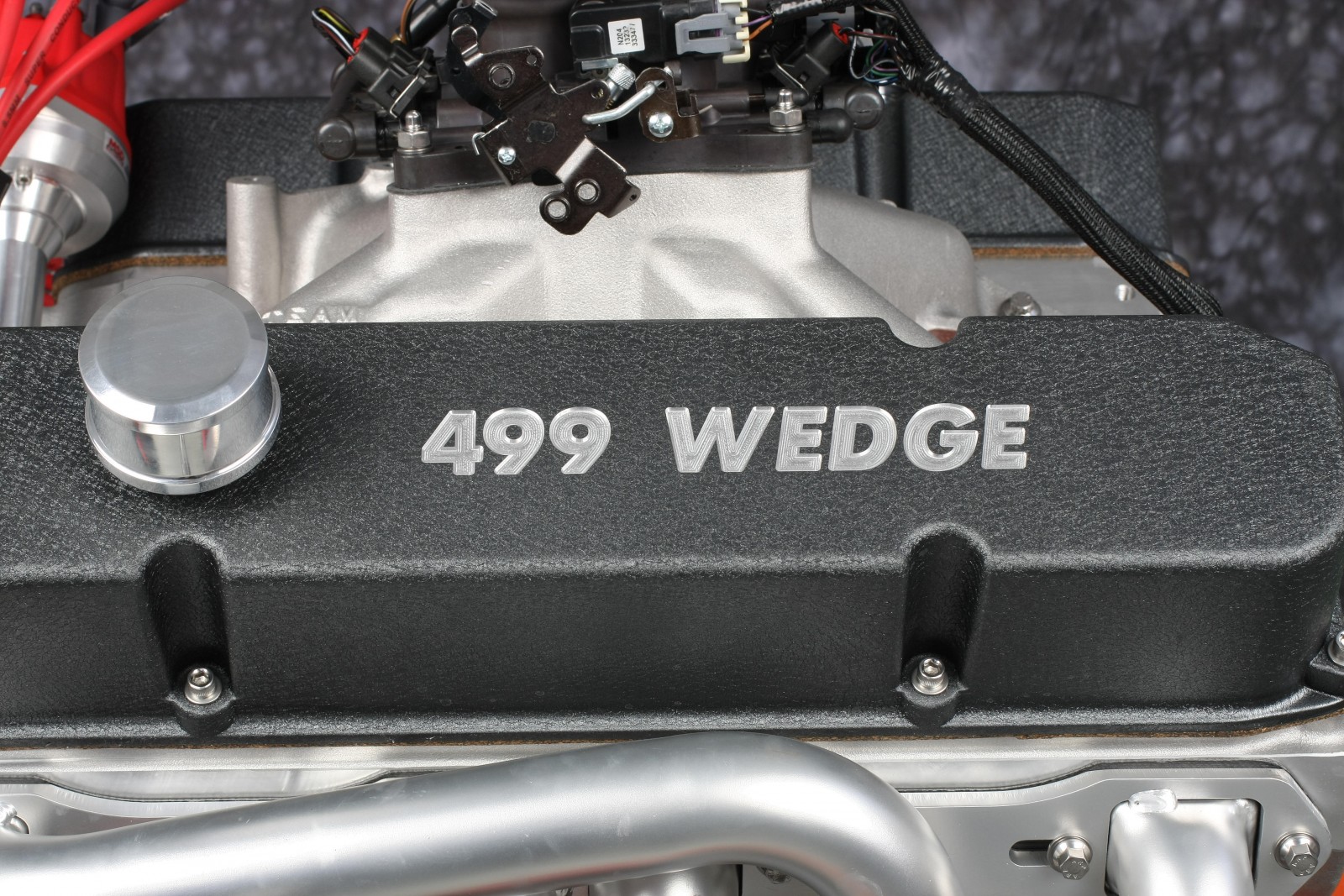
Valve Covers
I selected a pair of cast aluminum valve covers from Summit Racing. These tall style covers offer plenty of rocker arm clearance and a flat top that is ideal for engraving. I had the valve covers powdercoated in “silver splash,” a charcoal color that features a textured finish. I then had the covers CNC-engraved with “499 WEDGE” at Plate Engraving (Medina, OH).
Next Time
With the engine assembled, it’s time to see what 499 cubic inches of big block Mopar can do on the dyno. That’s what you’ll find out in the final installment of Mopar 499 Street Thumper!
What part number and manufacturer is the valley plate you used? The link to Summitracing just shows small block chivie. Not sure why as they don’t require them.
Jim, the valley pan was obtained from 440 Source, as were the billet aluminum valley pan end rails. Valley pan is part # 127-1011 and billet rails are #200-1042.
Thanks a bunch Mike!!!
I am going through the very same issues with the side spacing of the rocker to hold down clearance. Crane is telling me they don’t know why I’m having a problem everything should fit right out of the box . Mopar blue performance hold downs are too fat or Crane’s rockers are .I faced off every single hold down . They just would not allow the rocker to move enough to the side off centerline for the tip to be centered over the stem . Exactly what you had to do . You don’t know how satisfying this confirmation of my modifications is . They should have included this possibility in both the Crane and Mopars instructions . This ate up 4 weekends of frustration and many nights of restless sleep . Shame on them . They had to know . You are the man . Thanks
I have a question about quench. Most engines want around 0.040 to 0.060 for quench, but you oped for a very large 0.075. Would you have wanted a tighter quench? I quench that important on a low compression engine?
[…] Mopar 499 Street Hero (Part 3): Cylinder Heads, Valvetrain & External Parts – In Part One, we covered the 499 big block’s engine specs … heads, valvetrain, and external bolt-ons like the intake manifold, distributor, and water pump. Two popular cylinder head choices for a large cubic inch big block Mopar are Edelbrock’s … […]
[…] Read next: Mopar 499 Street Hero (Part 3): Cylinder Heads, Valvetrain & External Parts […]
i wish the questions asked where answered. Even if years later, it would help.