Editor’s Note: Mike Mavrigian has been building engines almost as long as there has been internal combustion. Mike’s shop, Birchwood Automotive, specializes in street performance and racing engines and vehicle restoration. As you’ll see in this article series, he includes a wealth of information on his engine builds.
NOTE: Updated 5/2/18 with oil pump intermediate driveshaft images, please scroll to the bottom of the story.
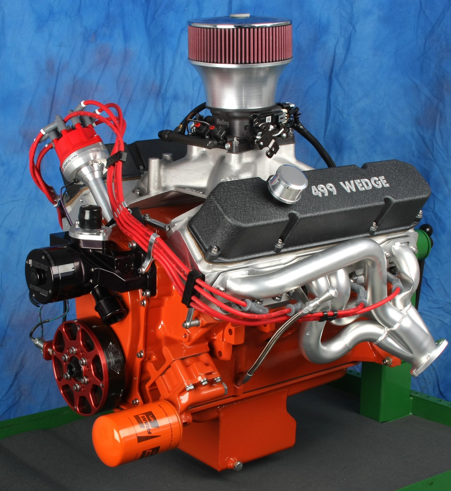
In Part 1, we covered the 499 big block’s engine specs and block prep. In Part 2, we’ll cover the rotating assembly, camshaft, oiling system, and other items to finish the short block.


A word about compression ratio before we continue with the build.
We planned to use Edelbrock Performer RPM aluminum heads with 88cc combustion chambers (EDL-60189). Those heads with the appropriate head gaskets would have yielded a 10.38:1 compression ratio on our short block. However, Edelbrock actually shipped the 84cc version (EDL-60929). Those small chamber heads push the compression ratio up to 11.7:1, which is too high for pump gas.
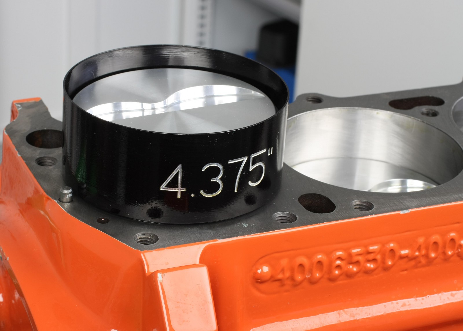
To fix the problem, I used pair of Cometic MLS heads gaskets with 4.500-inch bore openings and 0.040-inch compressed thickness. Combined with our block’s 4.3755-inch bores, 4.150-inch stroke, and flat-top pistons (with 5cc valve pockets and sitting 0.025 inch below the block deck) we got 10.6:1 compression, just within our safe limit for premium pump gas.
And now…on with the rest of our short block assembly.
Camshaft
My initial thought was to go with a solid roller cam, but Scott Koffel of Koffel’s Place talked me out of it. He noted that depending on the style of roller lifters, the lifter oil holes in the lifter bores can be exposed. That would require bushing the bores and modifying the oil passages. Koffel says he can actually obtain higher rpm with a flat tappet cam, so we went with his recommendation.
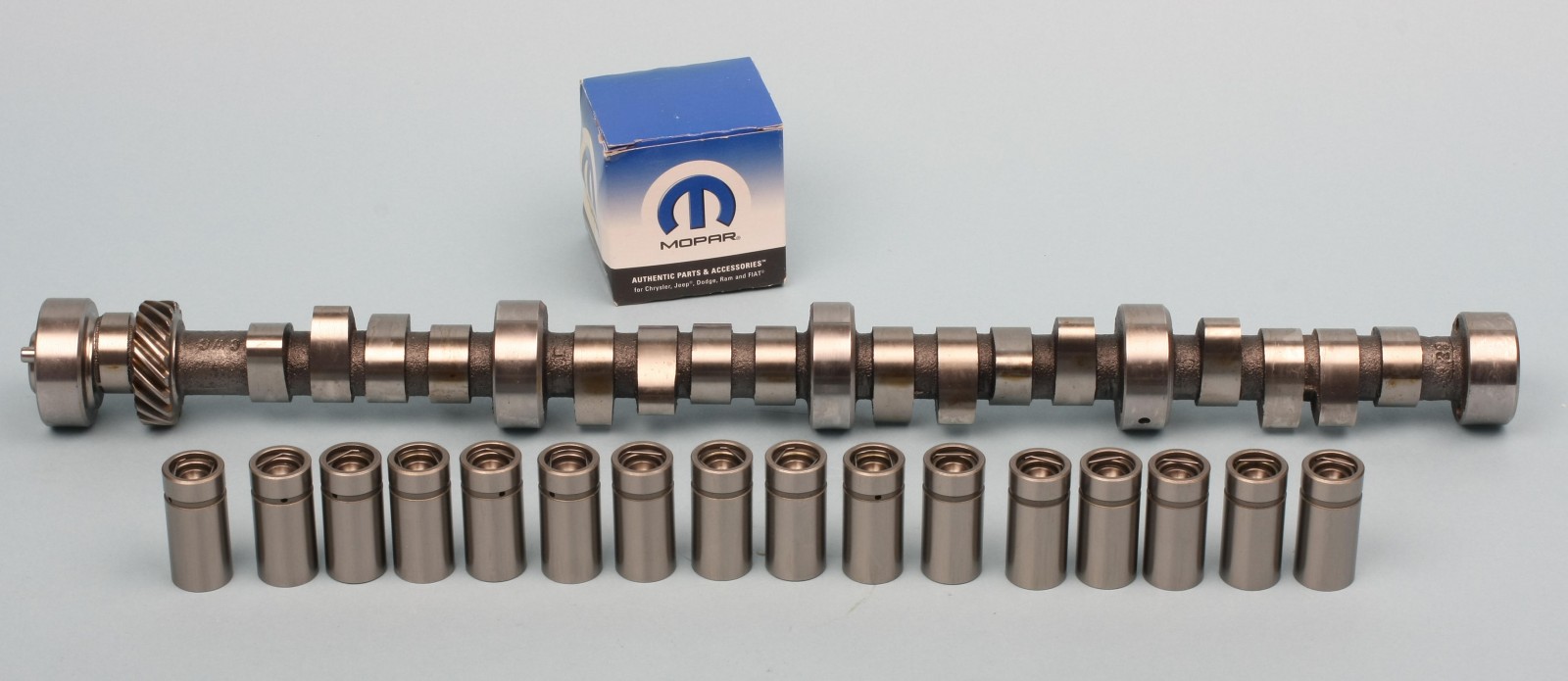
The Mopar Performance flat tappet hydraulic cam features 0.059-inch intake and exhaust lift (with 1.5:1 rocker arm ratio), 248/248 degrees duration at 0.050-inch, and a lobe separation angle (LSA) of 114 degrees.
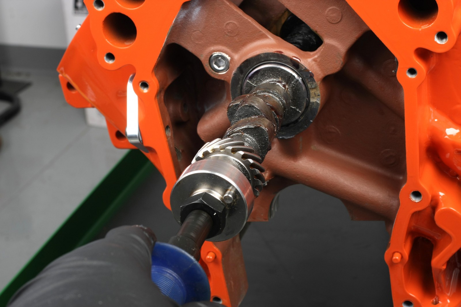
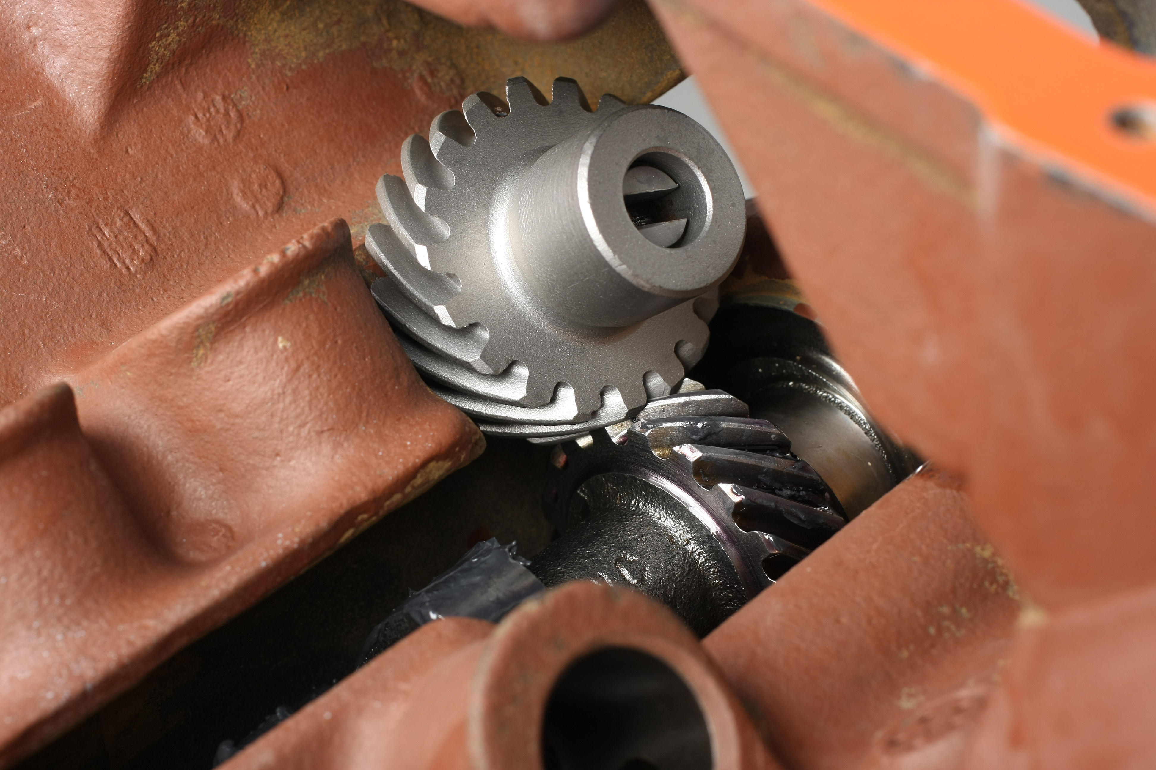
All journals, the distributor drive gear, and the sides of the lifters were coated with Royal Purple Max Tuff assembly lube. All lobes and lifter faces were coated with high-pressure moly lube. The cam was carefully installed to avoid nicking any of the bearings. Harsh scratches on new cam bearings can easily lead to a drop in oil pressure.
Crankshaft
Our Scat forged crank features a 4.150-inch stroke, providing an additional 0.770 inch of stroke as compared to a factory 440 crankshaft. The main and rod journals feature generous 0.125-inch radius fillets for added strength and measured exactly to spec. We also checked the crank for runout and as expected, there was none. The oil holes are neatly chamfered for efficient oil paths.
The Scat crank rear main journal’s seal area has a smooth surface that requires a neoprene-style rear seal. Cranks with a serrated rear main seal contact surface must use a rope-type rear seal. Using a neoprene seal will result in an oil leak due to eventual seal deformity.
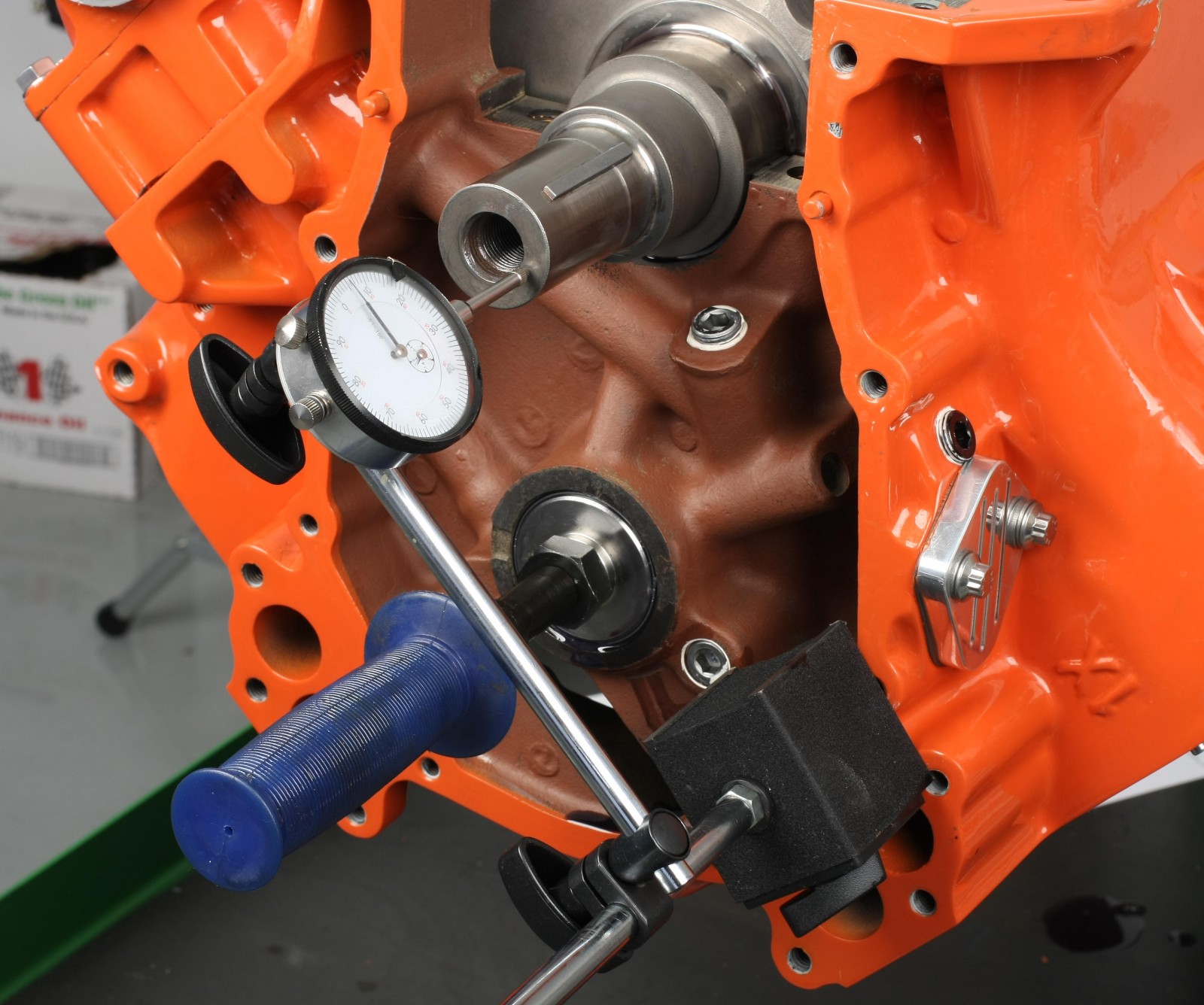
Initial test fitting for main bearing clearance was performed with all main bearings installed, ARP main studs hand-snugged to the block, and caps installed to 100 ft.-lbs. Main bearing I.D. came in at 2.6275 inches. Crankshaft main journal diameters measured 2.625 inch, providing a main bearing clearance of 0.0025 inch. Crankshaft thrust clearance was 0.005 inch, well within the Chrysler spec of 0.003-0.007 inch.
Balancing
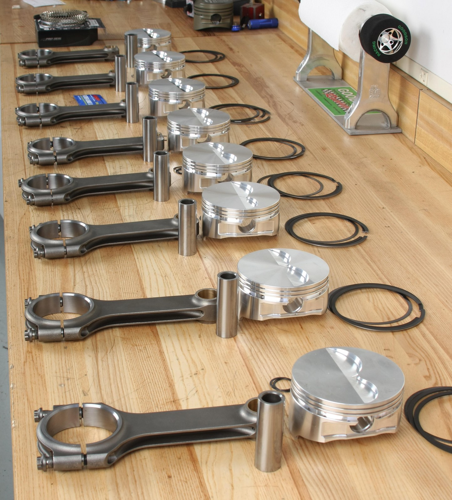
The JE pistons all weighed in within 0.5 of a gram and the Scat rods differed less than one gram rod-to-rod. We left them all as-is. Bobweights were made to match the total weight for pistons, piston pins, rings and support rails, pin locks, rod small ends, rods, rod bearings, and an allowance for oil.
The bobweights were installed on the crank for balancing. Weight removal was required on the front and rear crankshaft counterweights. The process took a while, but we got the crank to balance within 0.75 of a gram. The crankshaft is internally balanced, which means a zero-balance damper and flywheel are required. That means you can easily replace either the damper or crankshaft without the need for rebalancing.
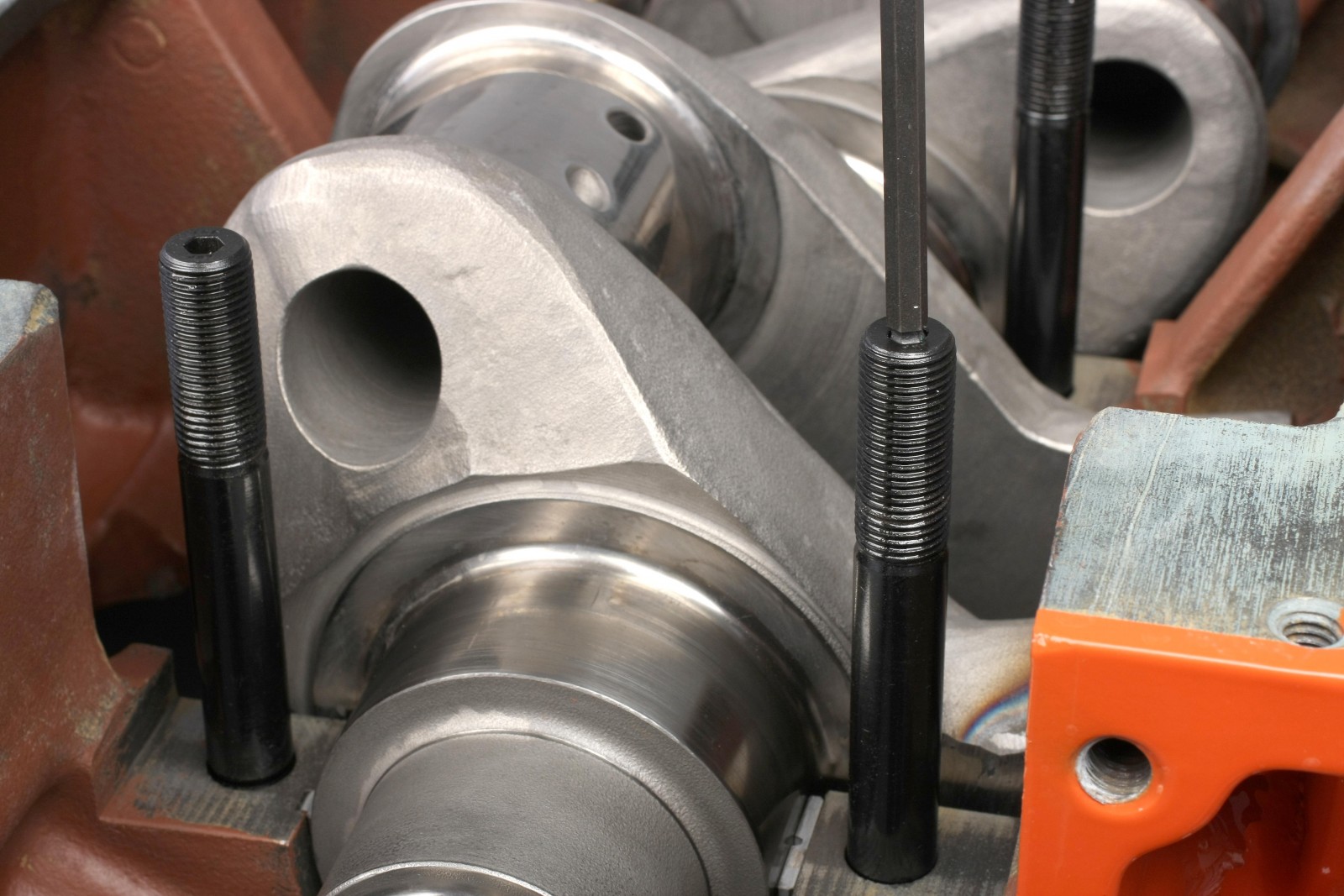
Crankshaft Installation
After a thorough cleaning, including scrubbing all oil passages with rifle brushes, the crank was laid into place in the block. The main bearing faces were coated with Royal Purple Max Tuff assembly lube prior to assembly.
We prefer installing the studs after crank installation to avoid scratching the crank on a stud. The half-inch ARP main studs were hand-snugged into place with a light coating of ARP moly on the upper threads. I tapped each cap with a plastic mallet to fully seat the cap registers. Stud nuts were initially tightened to 50 ft.-lbs., followed by a single sweep up to 110 ft.-lbs. ARP Ultra Moly was used on the threads.
There can be clearance issues between the #5 main cap studs and the windage tray. Make sure the exposed stud tips are flush with or shorter than the block’s oil pan rail. Our studs needed to be shortened by 0.175 inches.
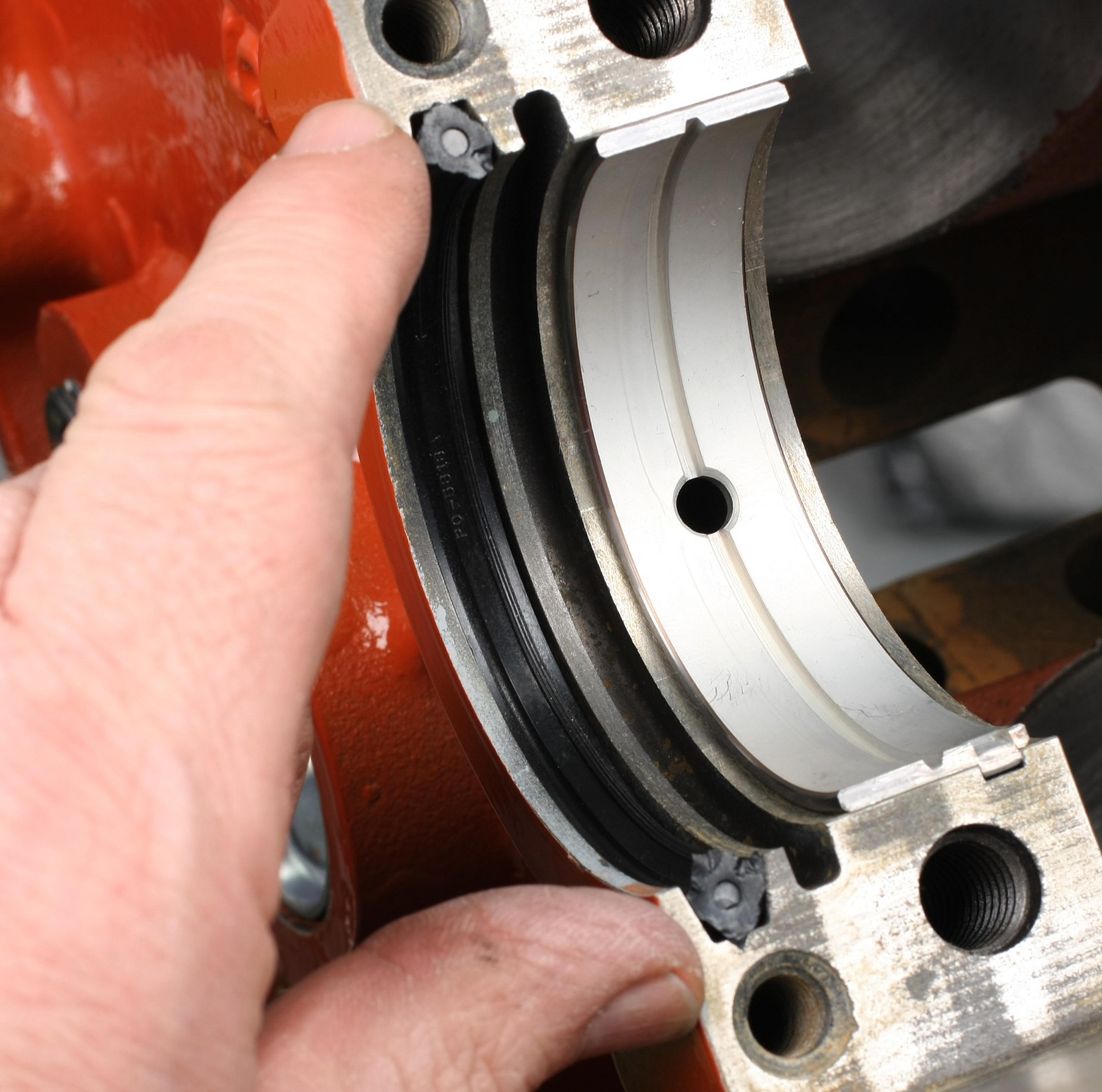
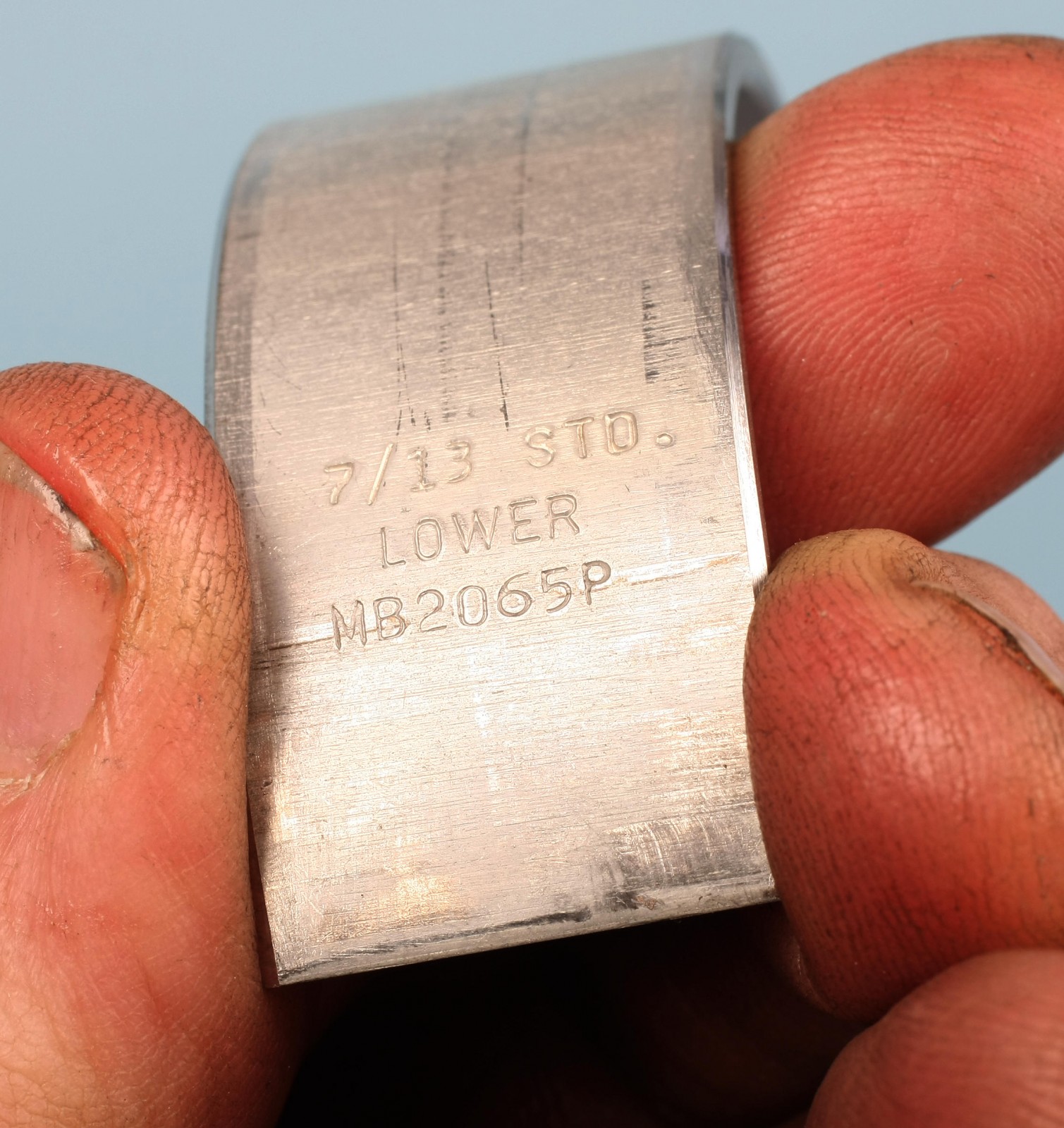
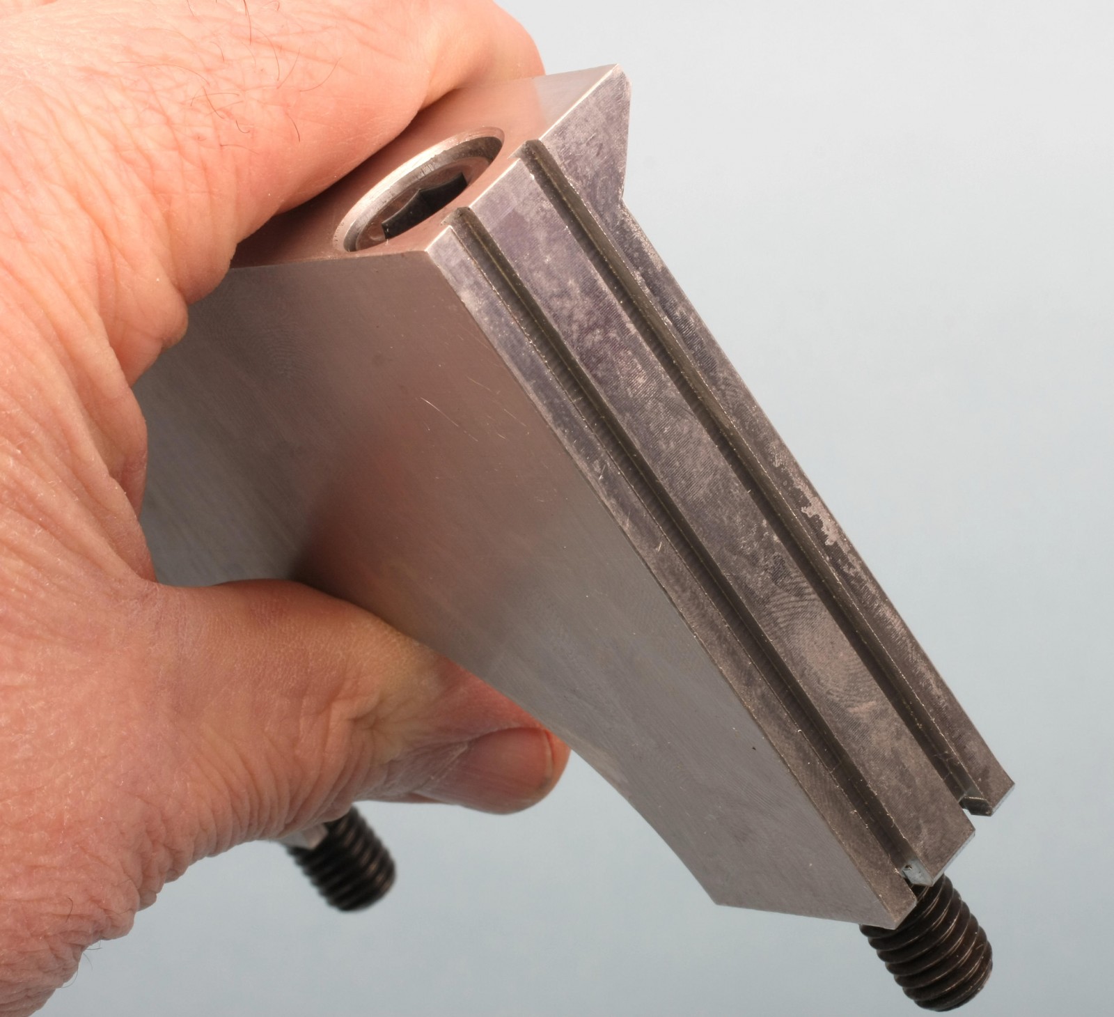
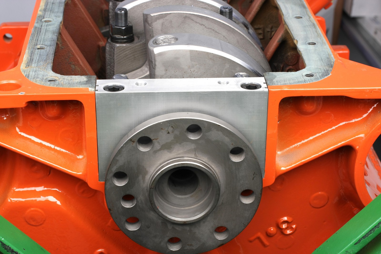
Big block Mopars use a separate aluminum rear main seal retainer that bolts to the block right behind the #5 main cap. The OE retainer housing is prone to cracking, so we purchased a machined billet piece from Mancini Racing. The kit includes a pair of locating pins to register the cap. The housing features a lower radiused seal and two straight square-profile “O-ring” seal strips on each side. We applied a light smear of RTV to the O-ring strips, the exposed ends of the radius seals, and the upper corners of the block where the seal housing rests. We filled the screw head cavities with RTV, flush with the lower surface of the cap. This is a trick that Scott Koffel showed us to help minimize the chance of oil leakage through the bolt passages.
Pistons and Rods
Our Scat H-beam connecting rods and JE pistons are designed for full-floating wrist pins retained by spiral locks (four per piston). To install spiral locks, gently spread the lock apart with your fingernails. Insert a tip of the lock into the groove in the piston pin bore, then use a small flat blade screwdriver to “walk” the spiral lock into its groove until the outer end snaps into place. Verify that each lock is fully engaged into its bore groove.
For a street performance build, we generally like 0.0008 to 0.0009 inch of wrist pin-to-rod clearance and 0.0009 to 0.0012 inch of pin-to-piston clearance. We got 0.0008 inch of rod bore clearance and 0.0009 inch at the piston.
Mopar cylinder heads have the following valve oriention front to rear (per chamber): exhaust/intake valve, intake/exhaust, exhaust/intake valves, and intake/exhaust. Make sure that the pistons are assembled with this valve orientation. Also pay attention to the rod big end orientation. The chamfered side of each rod big end always faces its adjacent crank journal fillet. The rod big end chamfers all face forward on the left side of the engine (cylinders 1, 3, 5, and 7). On the right side (cylinders 2, 4, 6 and 8), the big end chamfers all face rearward.
Piston Rings
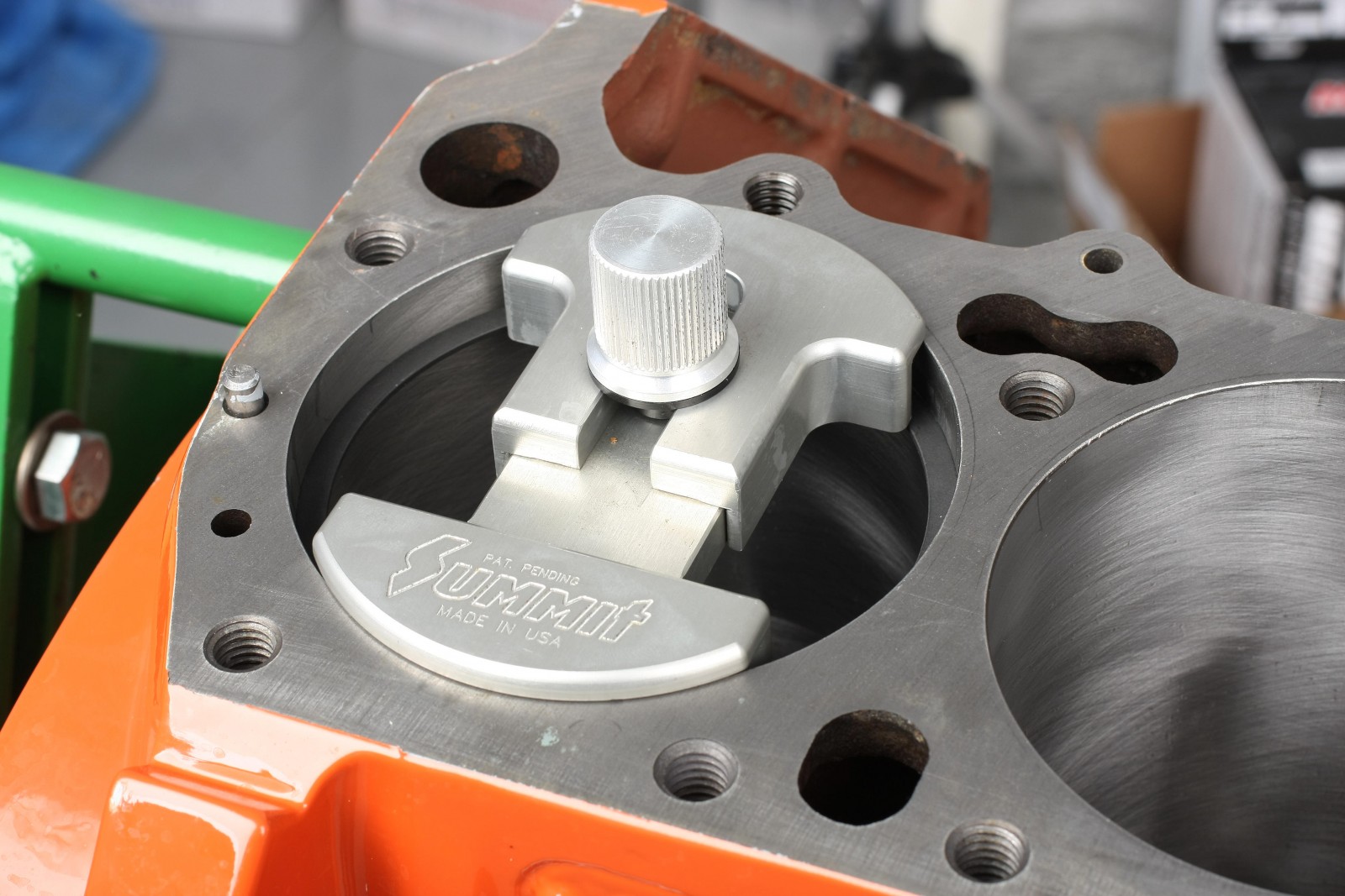
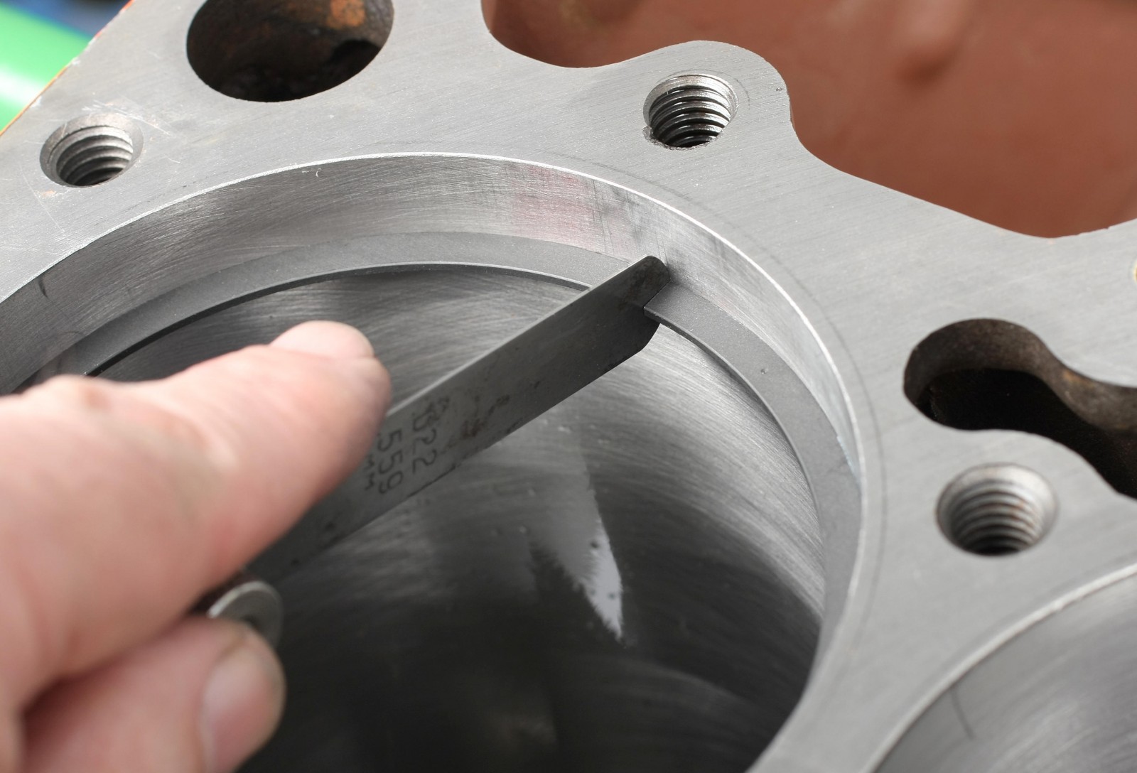
We test fit all piston rings to determine end gaps. Test-fitting our rings showed zero gap, requiring us to file the rings. For our engine, JE recommends a minimum top ring end gap of 0.0045-inch per inch of bore diameter and a second ring end gap minimum of 0.0050-inch per inch of bore diameter. For our 4.3755-inch bores, this calculates to a 0.01968-inch gap for the top rings, and 0.02187-inch for the secondary rings. We rounded those measurements and gapped the top rings at 0.020 inch and the secondary rings at 0.022 inch. We file-fit all rings for each cylinder instead of using one set as a reference for all rings.
Clearance between the top surface of each ring to the roof of the ring groove was checked; this is known as side or lateral clearance. The JE spec calls for 0.0015 to 0.003 inch. My measurements found 0.002 inch on each ring. Clearances of less than 0.001 inch can result in sticking of the rings inside the grooves.
Our pistons have an oil ring support rail where the piston pin bore intersects with the oil ring groove. That means the support rails will block pin entry, so the pistons were mounted on the rods before installing the ring pack.
The second and top rings were oriented so as not to allow end gap lineup. We generally place the gaps about 90 to 100 degrees apart.
Installing Piston and Rod Assemblies
The Clevite rod bearings were installed with Royal Purple Max Tuff assembly lube applied to the exposed bearing surfaces. The ARP rod bolts were treated to ARP Ultra Torque moly on the threads and the underside of the bolt heads.
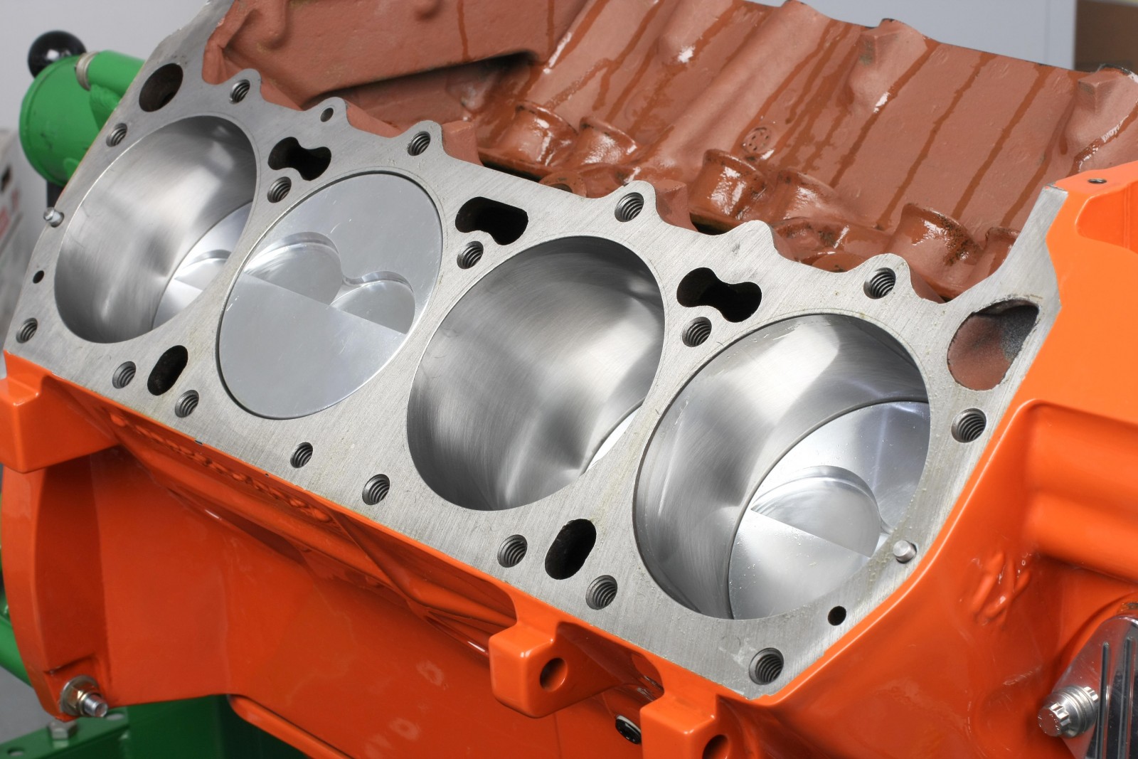
The cylinder walls were cleaned with lint-free white cloths and a fast-evaporating solvent (brake cleaner) until no traces of particles were evident. The cylinders were then coated with 30-weight engine oil.
We prefer using a one-piece machined ring compressor sized a specific bore diameter. Our ARP compressor made the job a breeze. With the piston skirts engaged into the top of the bore, we could actually push each piston fully into the bore with a closed fist while holding the compressor firmly against the block deck. Once a piston/rod assembly was in its bore, we installed the the rod cap and tightened the rod bolts with a ratchet and 12-point socket until the rod cap mated to each side of the rod big end.
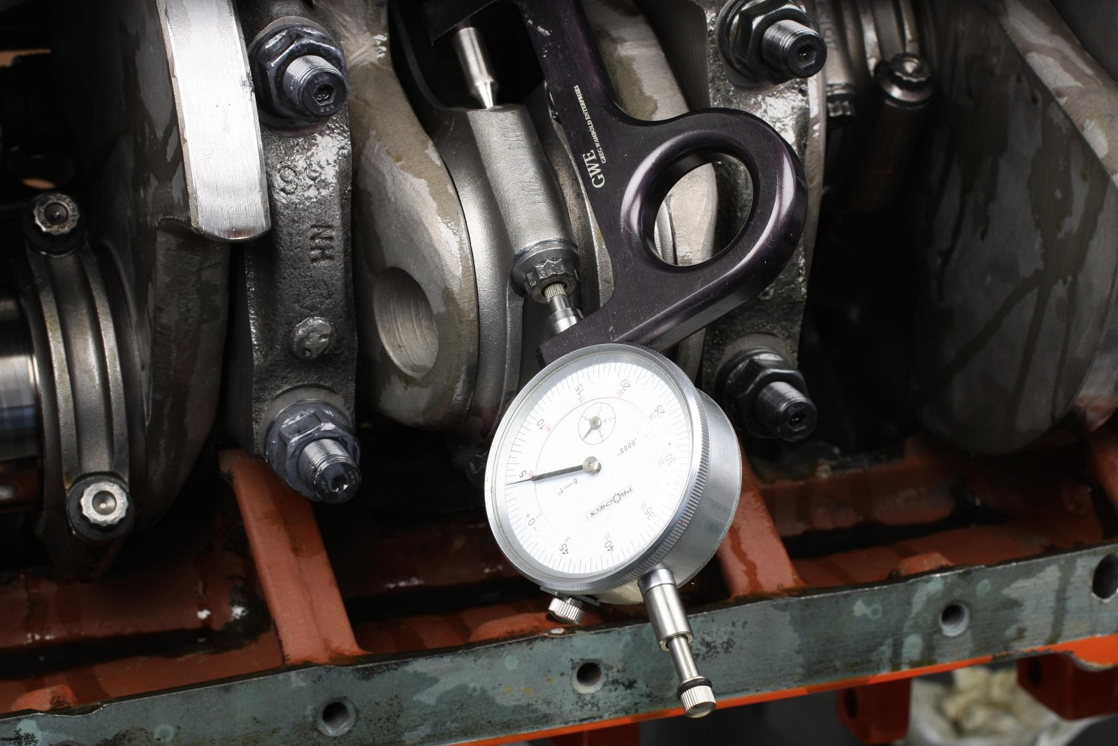
According to Scat’s instructions, the rod bolts (with moly lube) should be torqued to 64 ft.-lbs. and not exceed 0.0046 inch of stretch. Before installing the rod bolts, we checked each one on a rod bolt stretch gauge. At ARP’s 64 ft.-lb. torque rating, rod bolt stretch measured 0.00425 inch–well within range. Checking rod bolt stretch takes a few extra minutes as, but we feel that it’s time well spent.
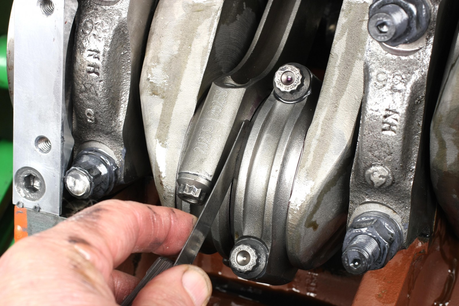
Once each pair of rods was installed its common journal, we measured rod sideplay using a feeler gauge. Spread the rod big ends apart with your fingers and insert the gauge between them. we measured 0.020 inches of sideplay.
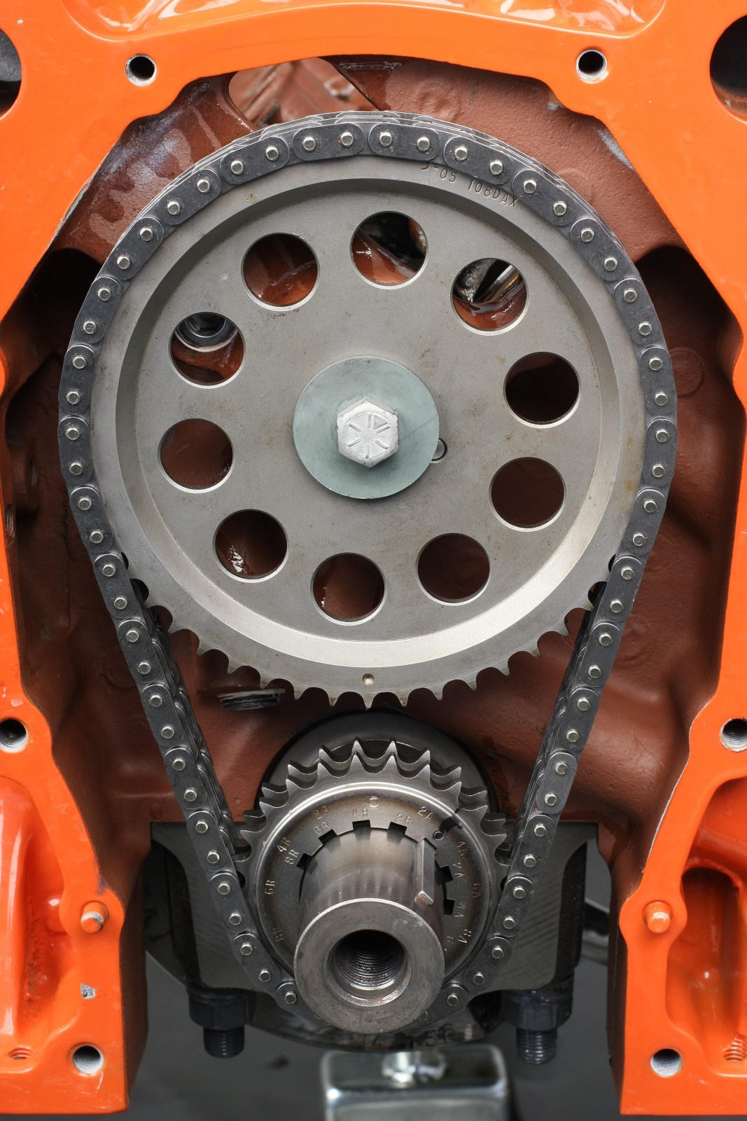
Timing Set
The Cloyes cam gear was a bit tight on the crank snout due to the cam dowel pin. This made installing the gear to the cam a bit tricky, but the result was a very nice fit of the double-roller chain with no excess slop. We installed the cam gear with a Grade 8 bolt that had a one inch long shank. This provided 7/16 inch of thread engagement with the OE cam bolt washer in place. The cam bolt washer features a slight convex surface on one side that must face outward, contacting the underside of the cam bolt head.
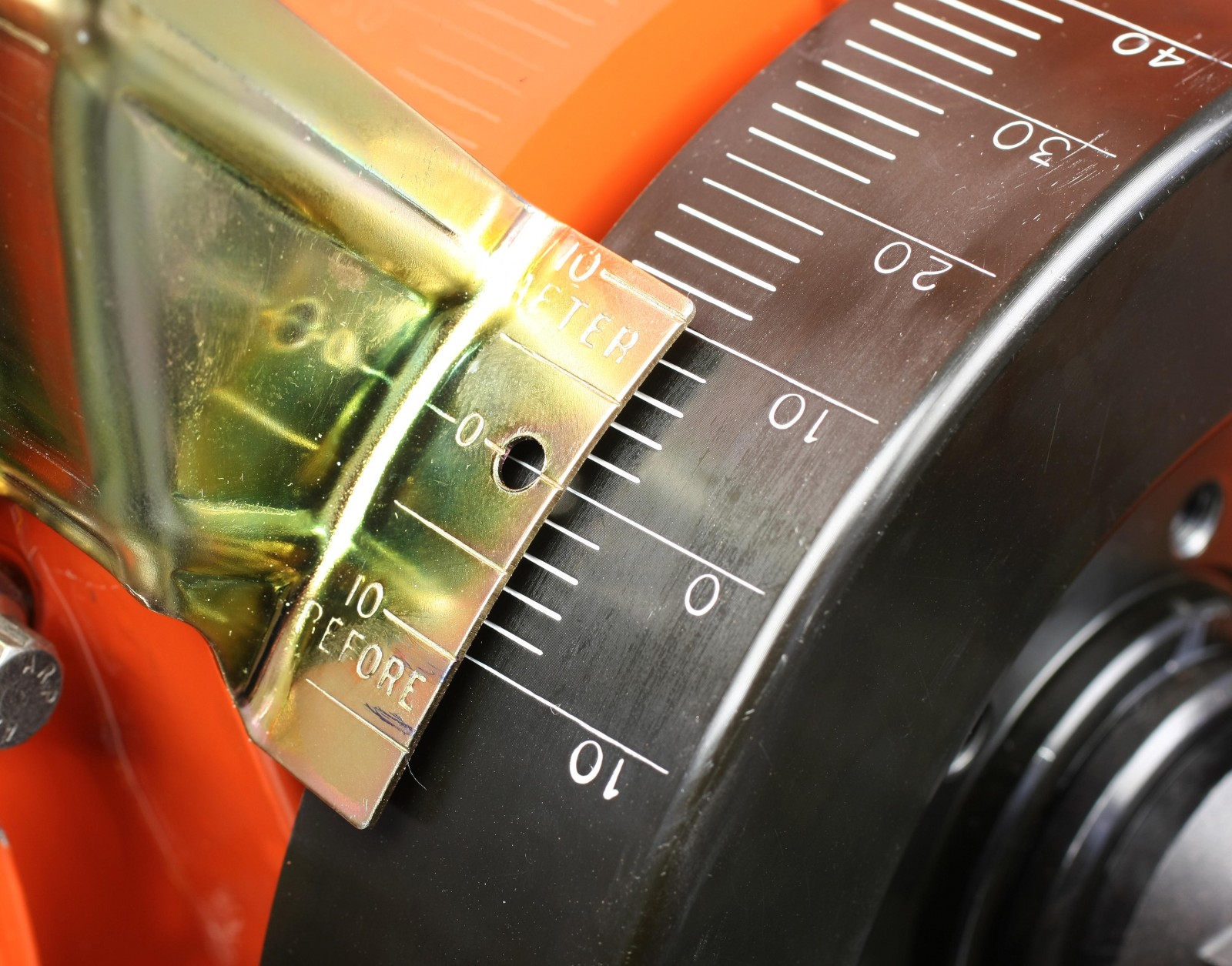
The Cloyes timing set allows multiple advance/retard increments of two degrees. We initially set the crank gear at zero in-line with the crank snout key. We aligned the outer zero timing mark on the crank gear to the timing dot on the cam gear. This places the cam gear dot at 6 o’clock and the crank gear’s outer zero mark at 12 o’clock.
Harmonic Damper
Our Fluidampr harmonic damper is a 7.25-inch diameter unit. The rear of the bore is slightly oversized to allow an easy slip-on fit. We used a bearing-equipped damper installer tool to slowly draw the damper into place until the rear of the flange contacted the front of the crank gear. Never install a balancer by striking it with a hammer or any other object. Most dampers feature a slight interference fit and must be drawn onto the crank snout evenly.
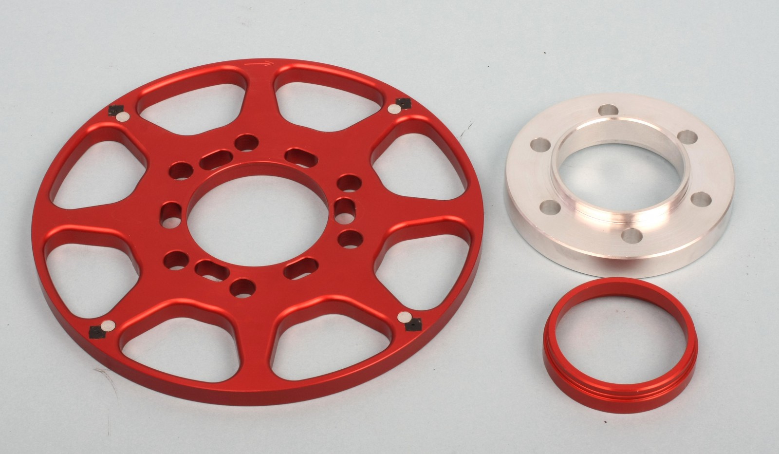
We also installed the MSD crank trigger system at this point. This allows a more precise timing to be read directly at the crank as apposed to the distributor (via the cam’s drive gear) and timing chain. The centering ring fit the damper and the trigger wheel perfectly, but didn’t protrude far enough out to engage the trigger wheel. Fluidampr machined a gorgeous aluminum adapter that extends out far enough to accept both the MSD centering ring and trigger wheel.
Oil Pump and Pickup
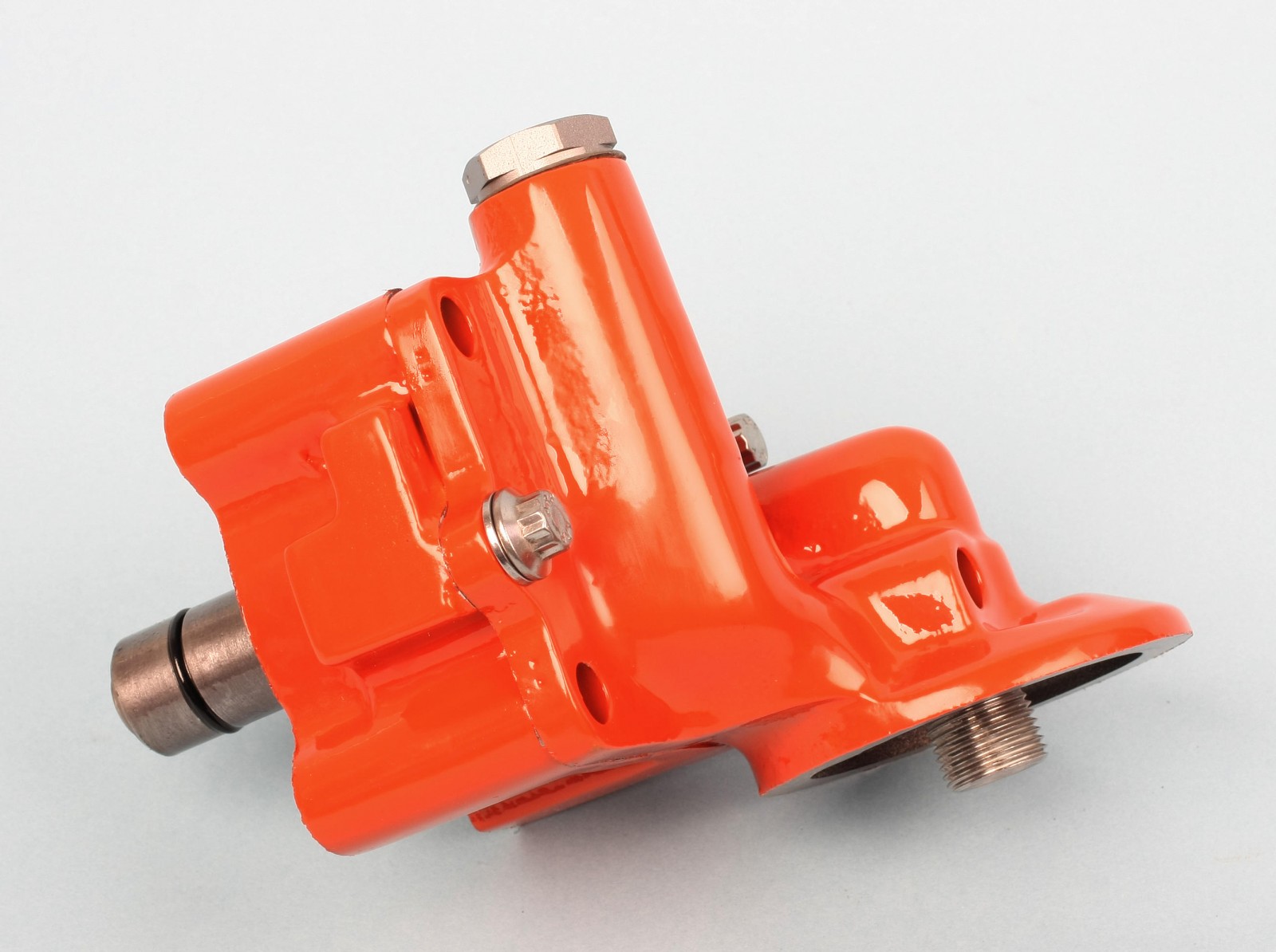
Our Melling Select M-63HV pump features 20-percent higher volume and standard pressure. If increased pressure is desired, shim the spring with a flattened quarter-inch lock washer. We carefully disassembled the pump and coated the rotors with Royal Purple Max Tuff assembly lube. We also smoothed out the exterior castings, then masked and painted them before reassembly. The housings are sealed with two O-rings. One O-ring goes on the drive boss before it’s installed in the block.
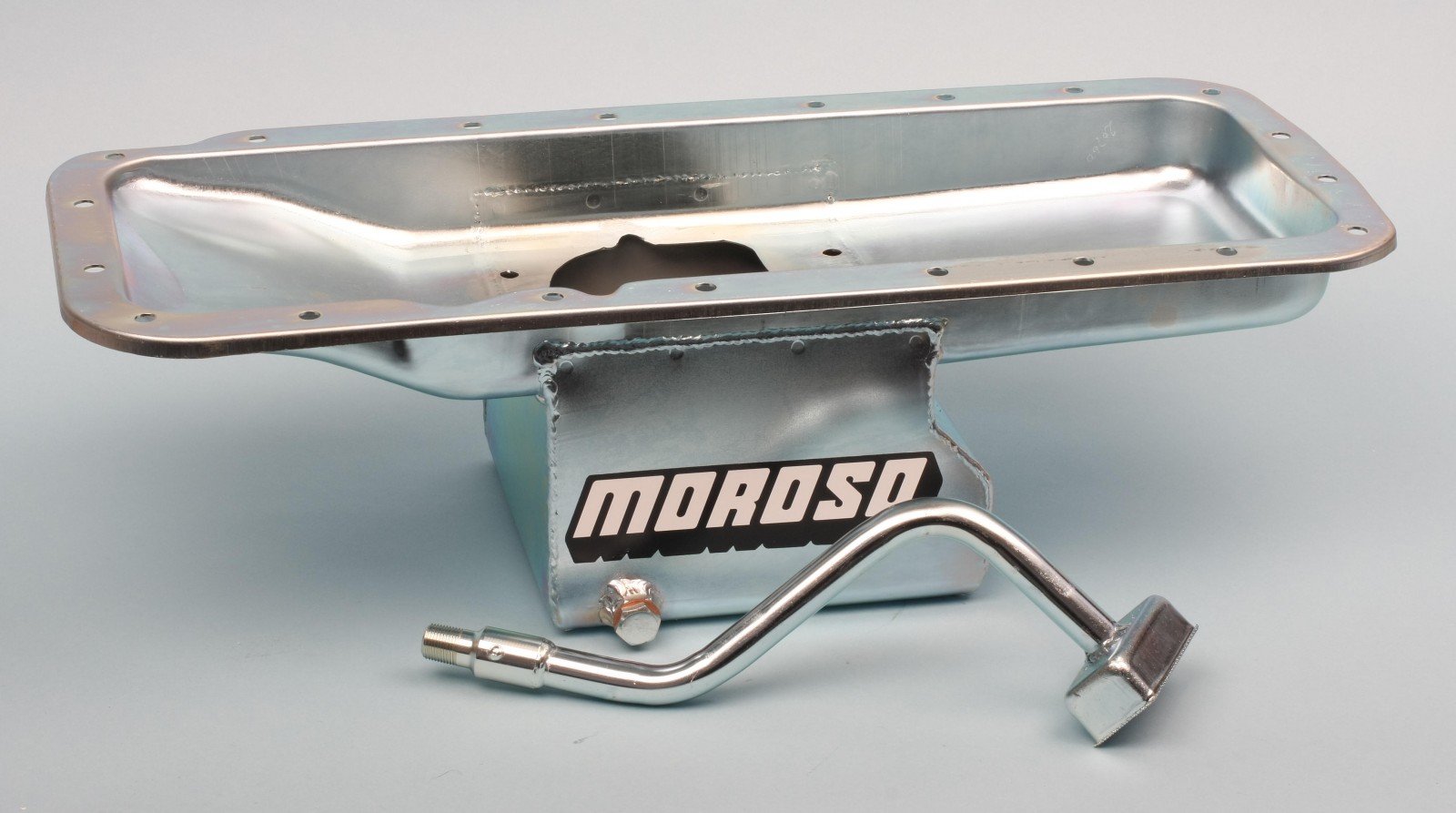
The Moroso oil pump pickup threads into a 3/8-inch NPT threaded hole in the forward left side of the block. PTFE thread sealant was applied to the pickup tube’s male threads. The pickup was hand-tightened to achieve a level position of the pickup screen.
Windage Tray and Oil Pan
Following Scott Koffel’s recommendation, we got a Mopar Performance windage tray. The windage tray sandwiches between the block rails and the oil pan. A gasket is required between the block and windage tray and one between the windage tray and oil pan. Before placing the block-to-windage tray gasket, apply a dot of RTV to the areas where the timing cover base meets the block. It was necessary to trim an opening in the windage tray to clear the the Moroso pickup tube.
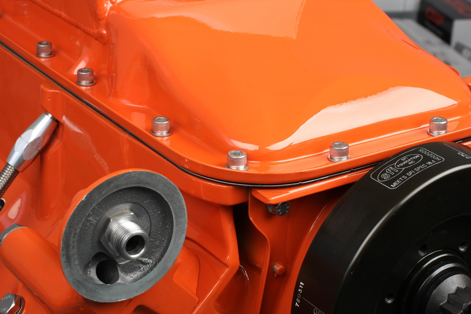
The oil pan is a 7-quart Moroso center-sump steel unit (MOR-20760). We find it helpful to temporarily install six or more 5/16-inch x 18 studs in the block rail to help align the gaskets, windage tray, and oil pan as a package. Replace the studs with bolts as you snug down the pan.
Don’t fully tighten the timing cover bolts before installing the windage tray and oil pan. Snug the oil pan bolts, which may slightly pull the timing cover towards the pan rail, providing a more even gasket mating surface between the timing cover and pan. Even though the timing cover is registered with two dowel pins, there may be a slight amount of movement available.
Other Parts
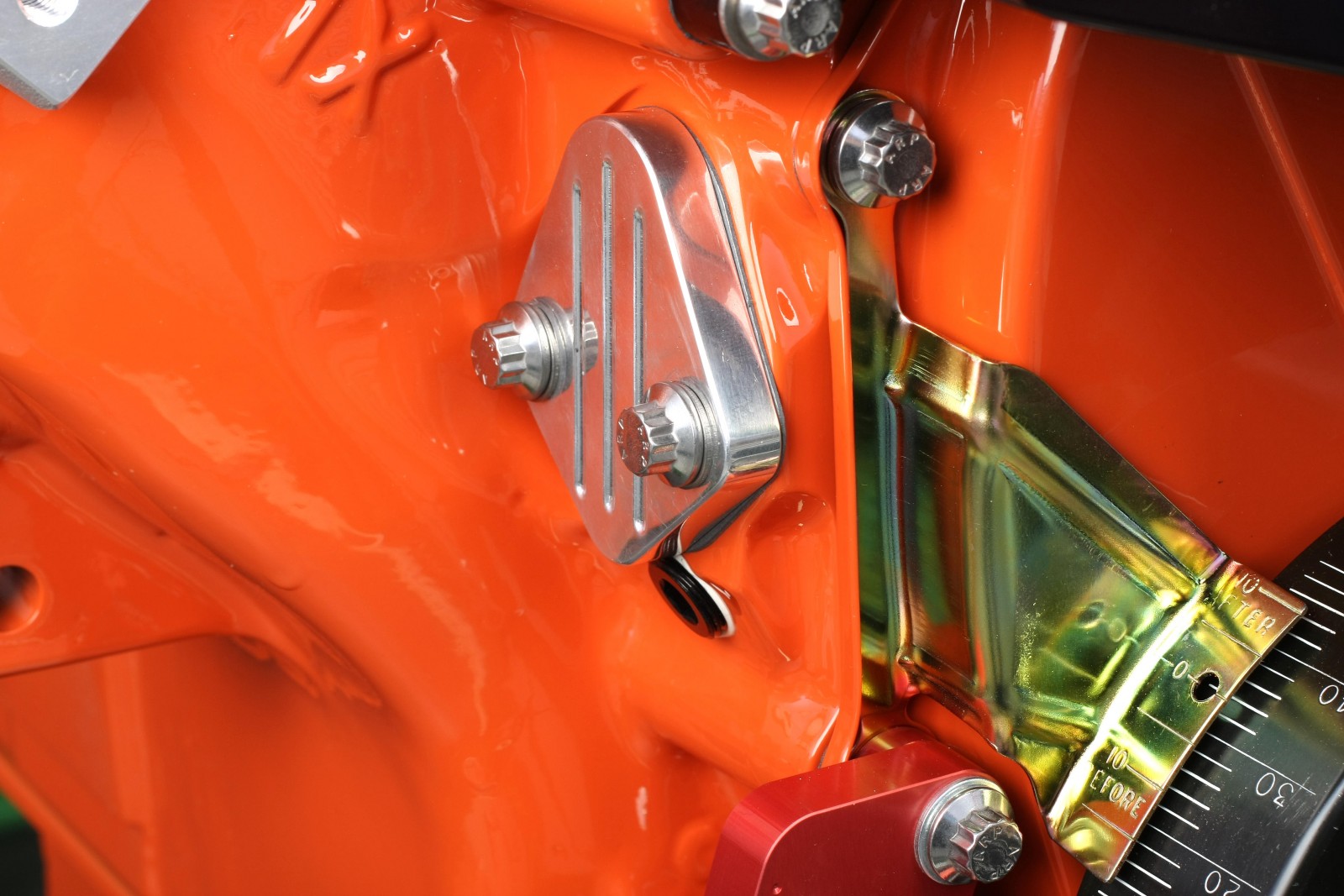
Since we needed to run an electric fuel pump to feed our Holley Terminator EFI system, we installed a Summit Racing mechanical fuel pump block off plate (SUM-G243). This plate fits big block Chevys; for installation on a big block Chrysler, the rear corner of the plate needs to be shaved slightly for clearance. This is due to the block casting’s raised area at the rear of the fuel pump boss machined flat surface.
We also installed a top valley tray. It is held captive under the inboard edges of the cylinder heads, so it must be installed first. This valley cover must be sealed with RTV. We carefully masked off the exposed areas that run parallel to the heads, as well as the front and rear of the block under the valley cover. This allowed us to wipe off any excess RTV after installation, without smearing it on the heads, the painted surface of the valley cover, or block.
Read next: Mopar 499 Street Hero (Part 3): Cylinder Heads, Valvetrain & External Parts
***Update May 2, 2018***
Reader Eric T. asked:
“I have yet to see the installation of the oil pump intermediate driveshaft bushing on any rebuild of any RB mopar engine what gives?”
Here are some pictures to answer that question.
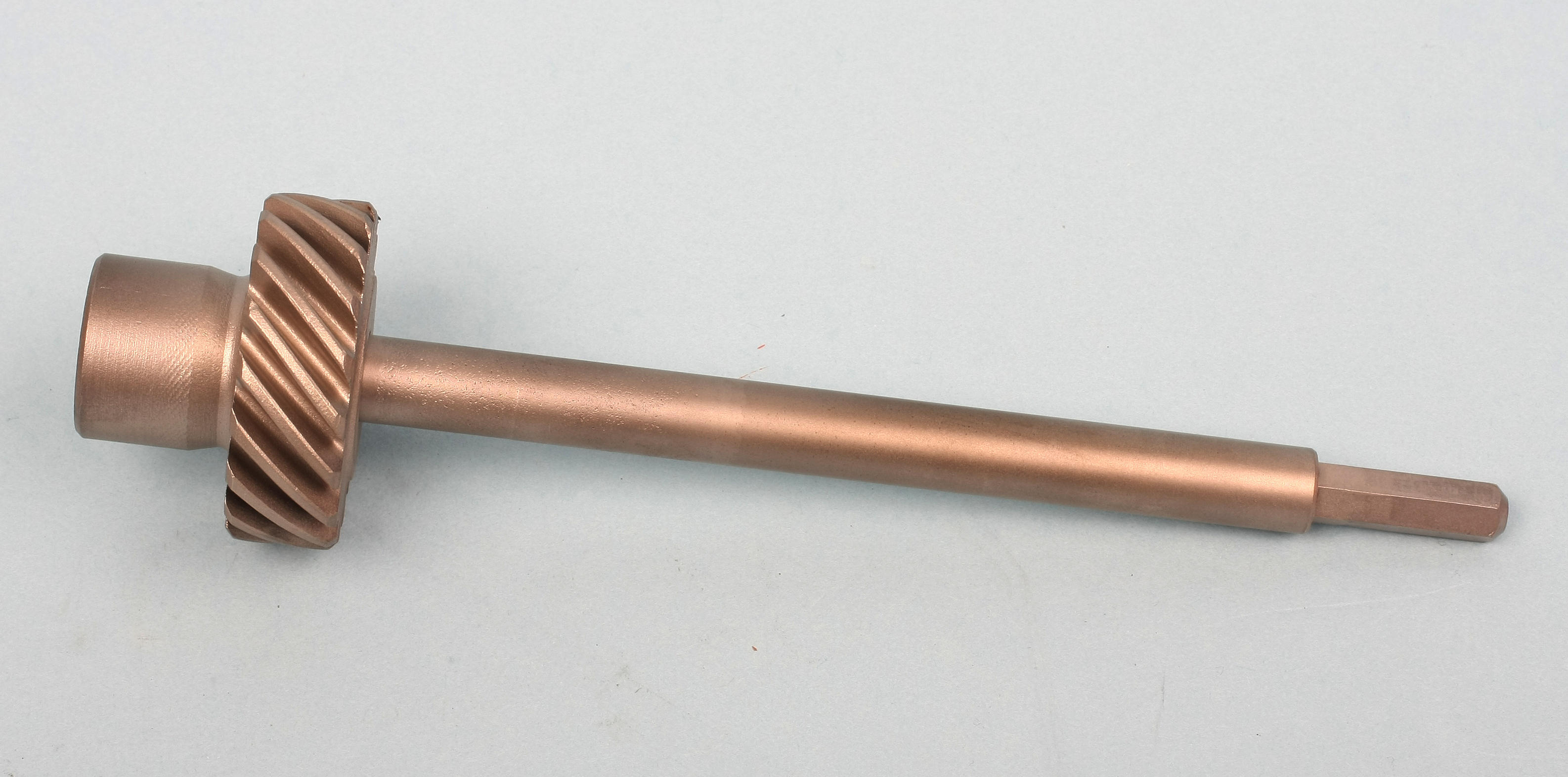
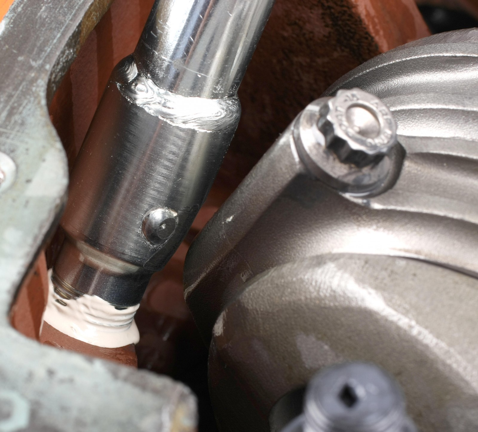
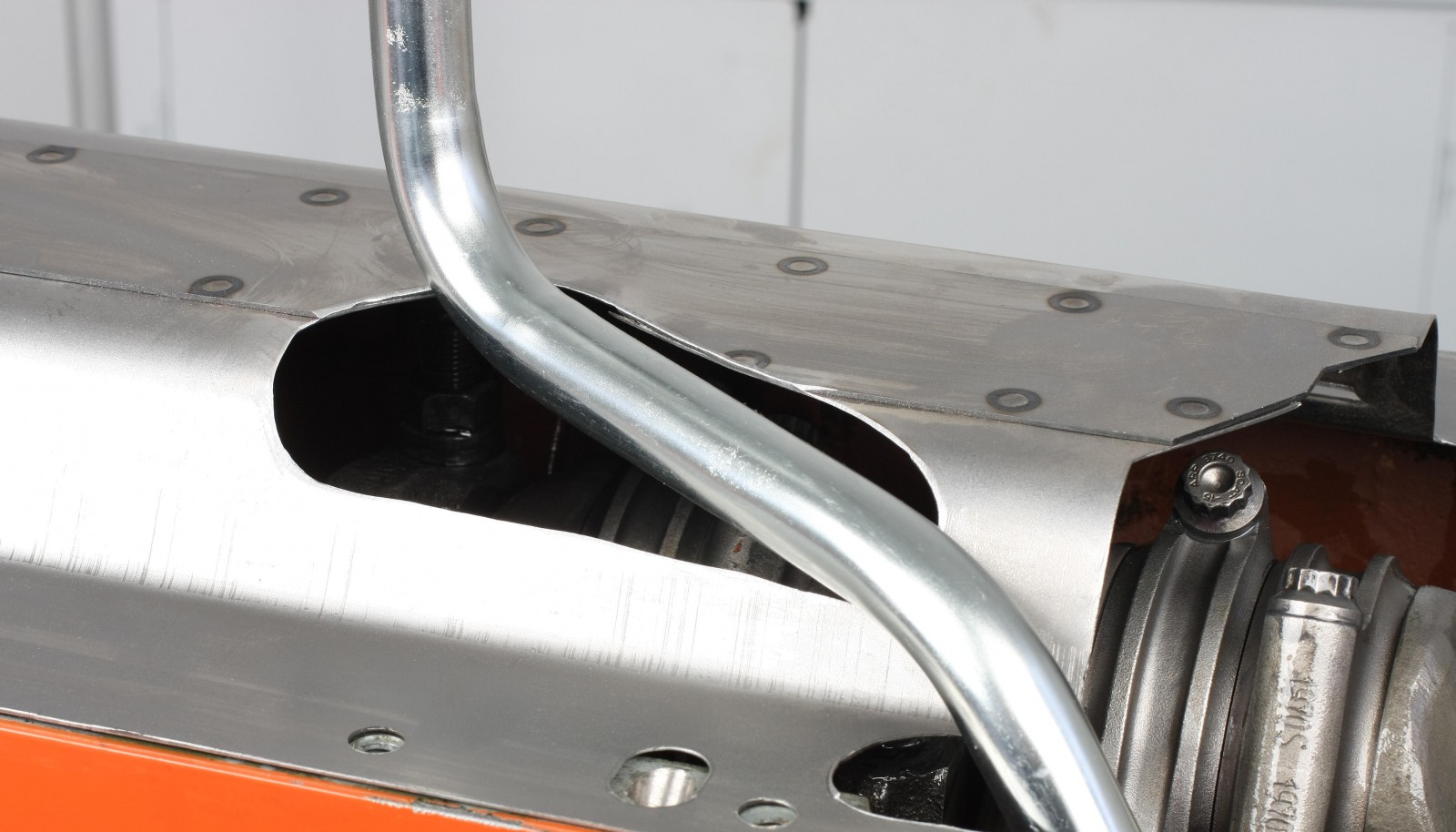
This is the oil pump intermediate driveshaft shaft used on the Mopar 499 Street Thumper build. (Image/Mike Mavrigian)
This is the oil pump intermediate driveshaft installed. (Image/Mike Mavrigian)
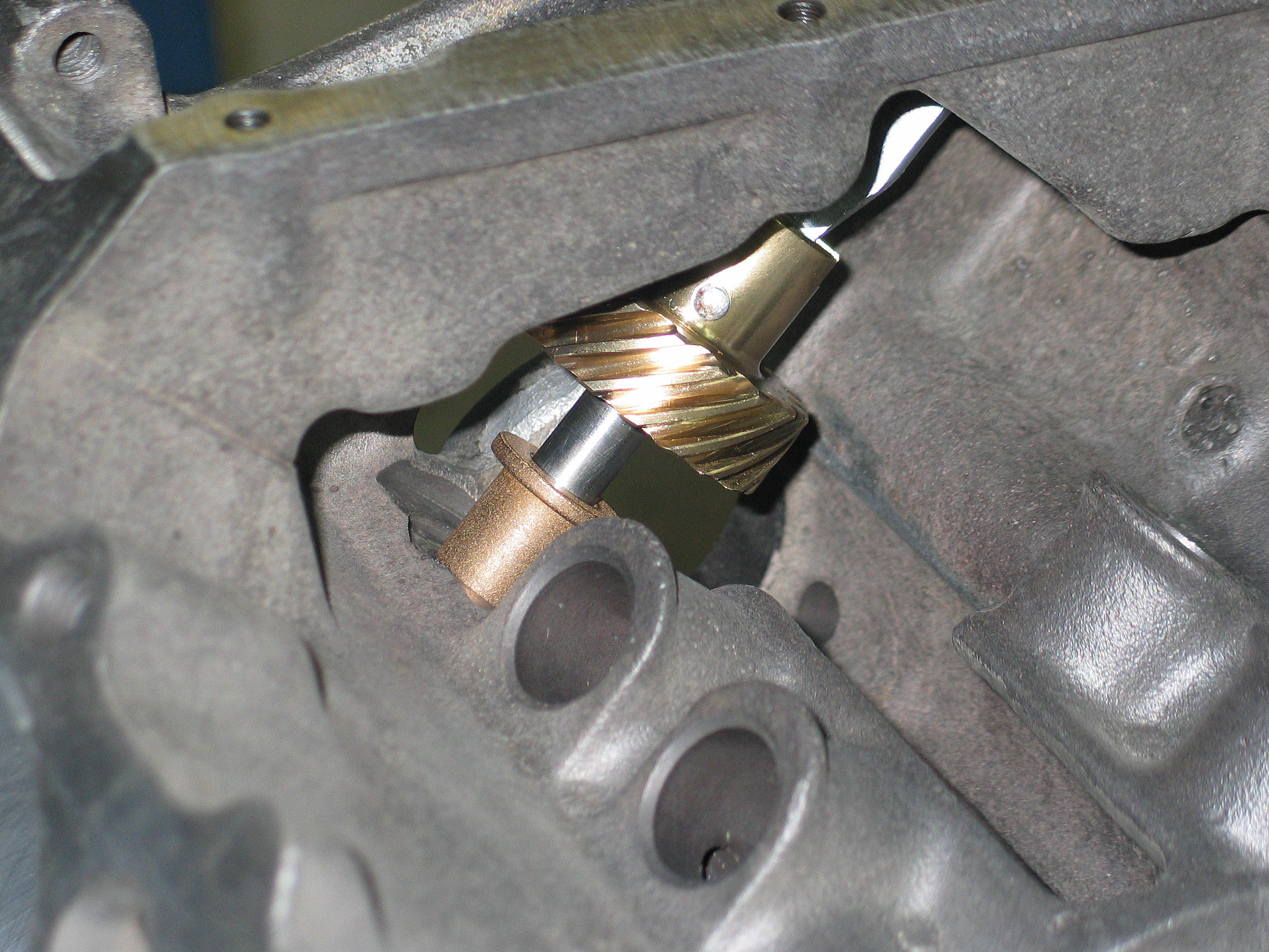
A new bronze bushing was installed for the oil pump intermediate shaft. Here a pre-sized bushing is installed, driving it into the block using a spare intermediate shaft as the guide. (Image/Mike Mavrigian)
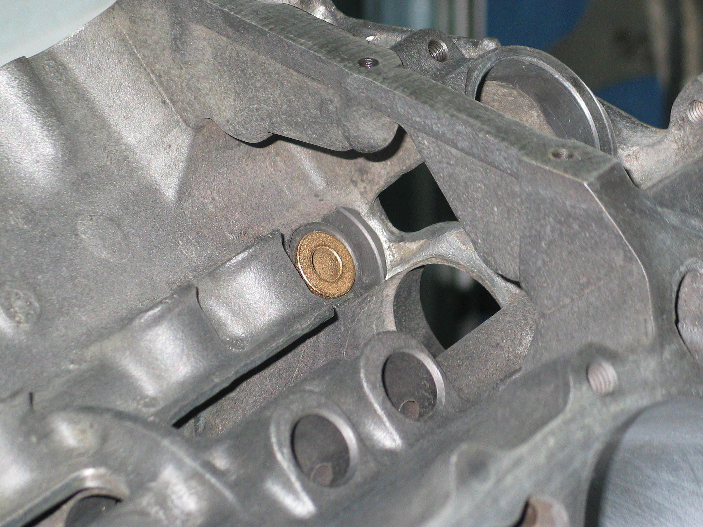
The installed bronze shaft bushing will accept the intermediate shaft without the need to hone the bushing to size. (Image/Mike Mavrigian)
I have yet to see the installation of the oil pump intermediate driveshaft bushing on any rebuild of any RB mopar engine what gives?
Hey Eric, thanks for reading and sorry for the delayed response. We added some additional pictures from Mike Mavrigian to answer your question–scroll down to the bottom of the story.
[…] cover the rotating assembly, camshaft, oiling system, and other items to finish the short block. In Part Two, we showed you the short block assembly. In Part Three, Mike assembles and installs the cylinder […]
[…] Part Two of Mopar 499 Street Thumper, we’ll cover bottom end assembly, camshaft selection and degreeing, […]
[…] cover the rotating assembly, camshaft, oiling system, and other items to finish the short block. In Part 2, we showed you the short block assembly. In Part 3, Mike finished the build with cylinder heads, […]
[…] (Image/Mike Mavrigian) […]
Great pictures. But I’m really interested if the special installation tool must be used to expand and burnish the bushing, or was that just for the original factory aluminium bushing and not needed for the new aftermarket brass bushings? Seems there is some contraversy about the correct way to install the bushing.
Sorry, you did answer my questions. I was reading this article on a cell phone outside in the sun and did not see the lighter colored text under the pictures. Thank you so much, you guys are fantastic.
Eric T
Hi,I was removing my oil pump drive bearing ,it didn’t go to plan & fell down instead off coming up & out. My question is would it of dropped into sump or gone somewhere else eg into oil gallery ? Thanks.