For turbo LS folks (actually, any turbo enthusiast), the question is sometimes not just boosted power, but also boost response.

Turbo folks always love the power production, but the only thing better than power is power RIGHT NOW! The surge of torque that accompanies boost is amazing (and unfortunately addictive). Too many turbo combos have succumbed to the notion that if a little boost is good, ALL the boost must be even better. This possibility notwithstanding, boost is still the best way to make more power with any motor, and the mean streets are currently chalk full of junkyard turbo LS builds.

Talk to any turbo owner and chances are good that boost response comes up. Second on the list to absolute power is always response. What do we want? More power? When do we want it? Right now.

While turbo sizing and naturally aspirated torque (low speed specifically) production are the two major contributing factors to boost response, other things can be done to help boost building on your turbo LS.

One area of contention is how the exhaust energy is provided to the turbo, meaning the exhaust manifolds themselves.

ls engine on a dyno test pull
What works better for boost response on your turbo LS, tube headers or log manifolds? (Image/Richard Holdener)

Given the need for things like packaging, converter light off (emissions), and longevity, most factory turbo motors rely on cast manifolds. The side benefit of this design is often response rate, but much of this (at the OEM level) comes from the turbo sizing as well.

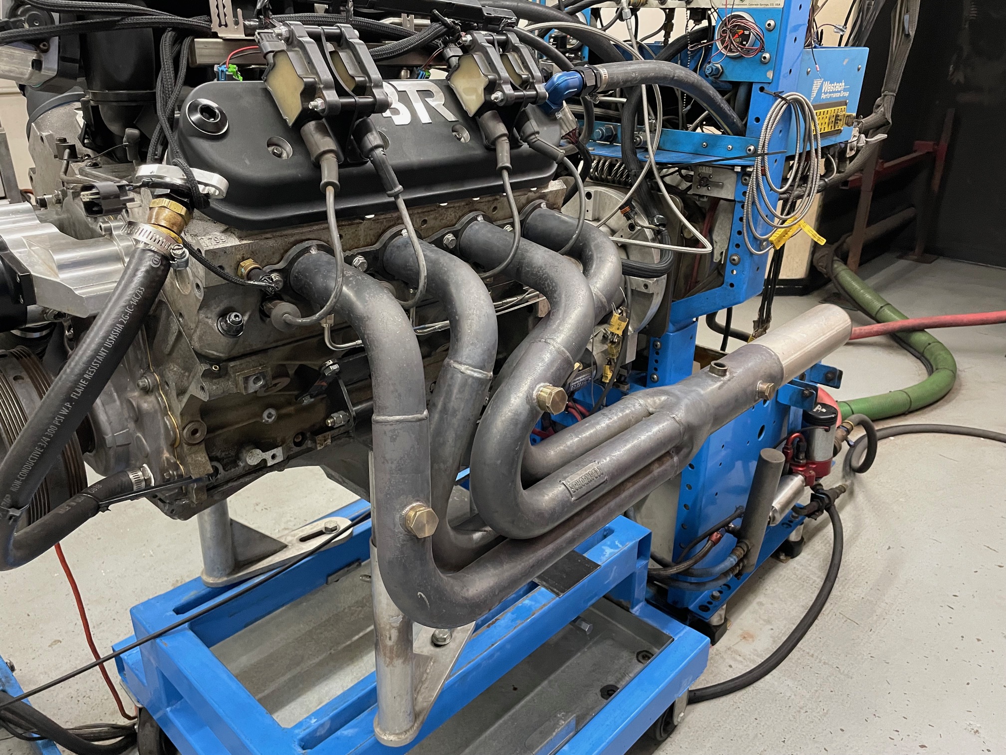
For aftermarket use, these concerns are less important and this opens up the possibilities for different exhaust manifold designs. For most of us, the two major players are some type of log-style manifold (often created using schedule 40 or similar tubing) and typical tubular headers. The aftermarket is full of header offerings for LS motors, but if going this route, choose them not just for looks or flow, but also for fitment in your chassis.

The question then becomes, which one should you choose, is one style really better than the other? While it would be necessary to define “better” here, for our needs, we focused on response rate, meaning which design started making boost sooner. It should be pointed out that this test is something less than a universal header vs log manifold. Different specific designs of each might have different response rates, but here we go (with a curve ball thrown in no less).

The first hurdle to clear was to devise a test to demonstrate boost response. Sure, we could strap a motor down and run both systems, but the limitations of the engine dyno (stationary load) meant if there was minimal difference between the two with a given size turbo, we might not see much of a difference. Basically, we needed the manifolds themselves to have a bigger stake in response rate.

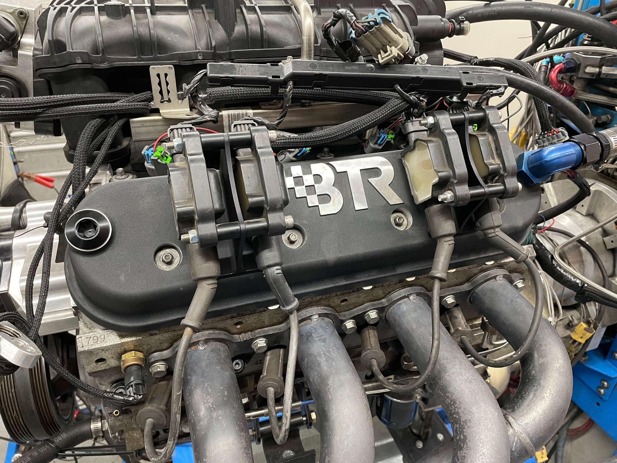
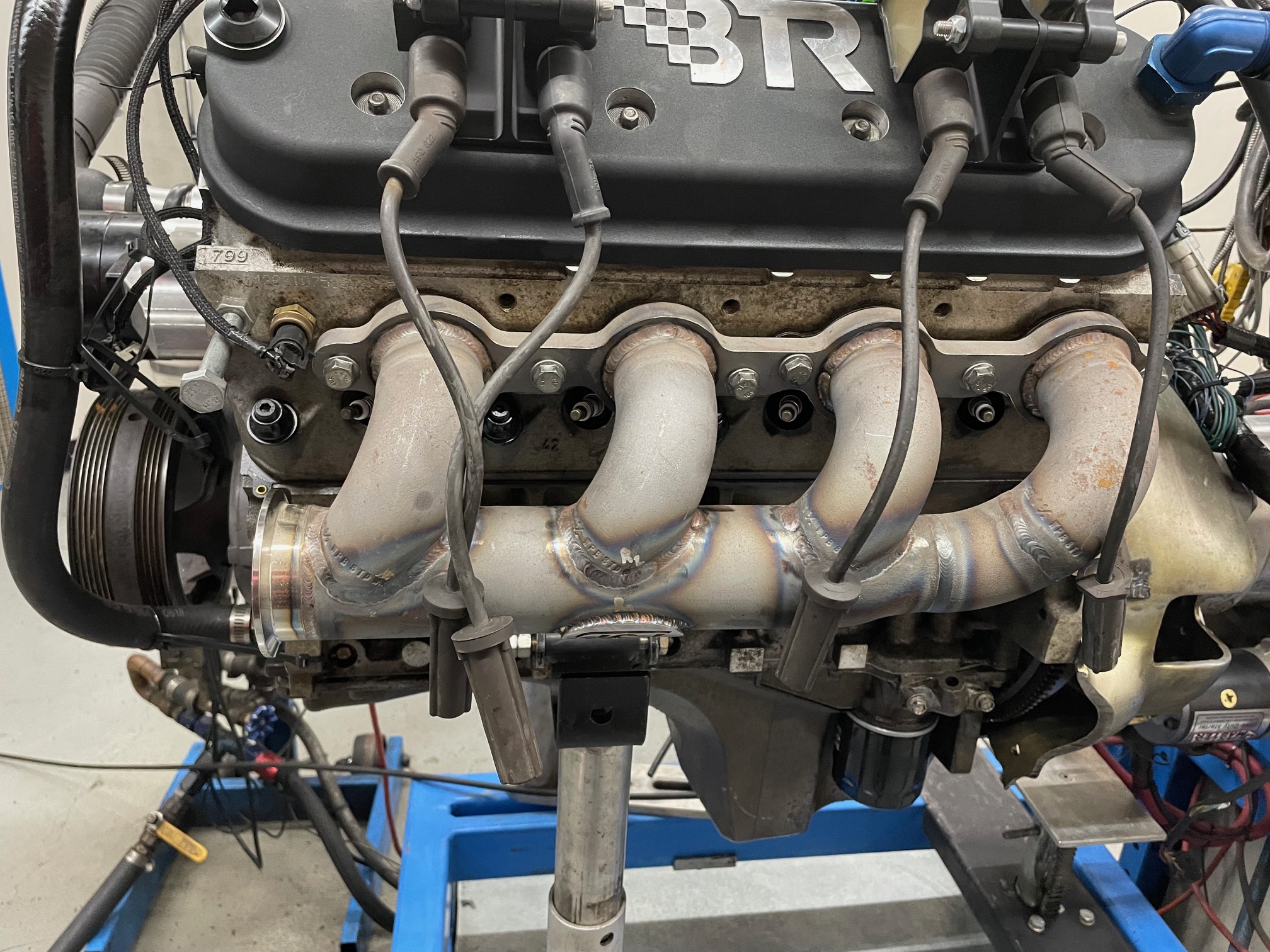
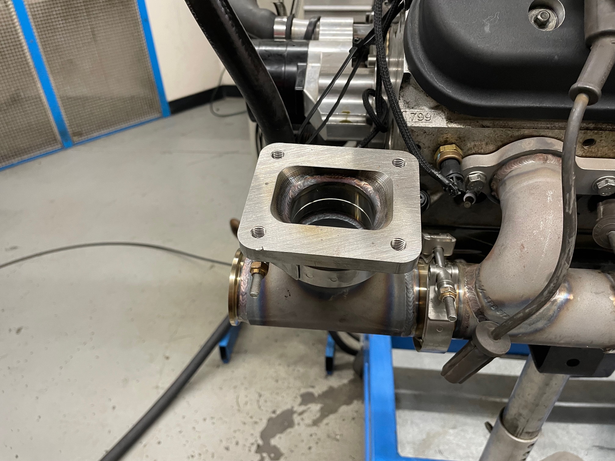
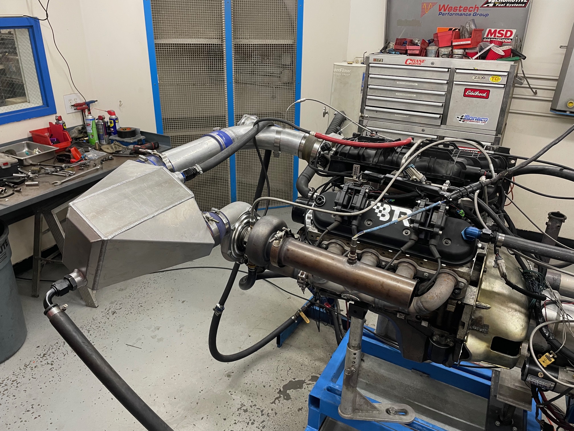
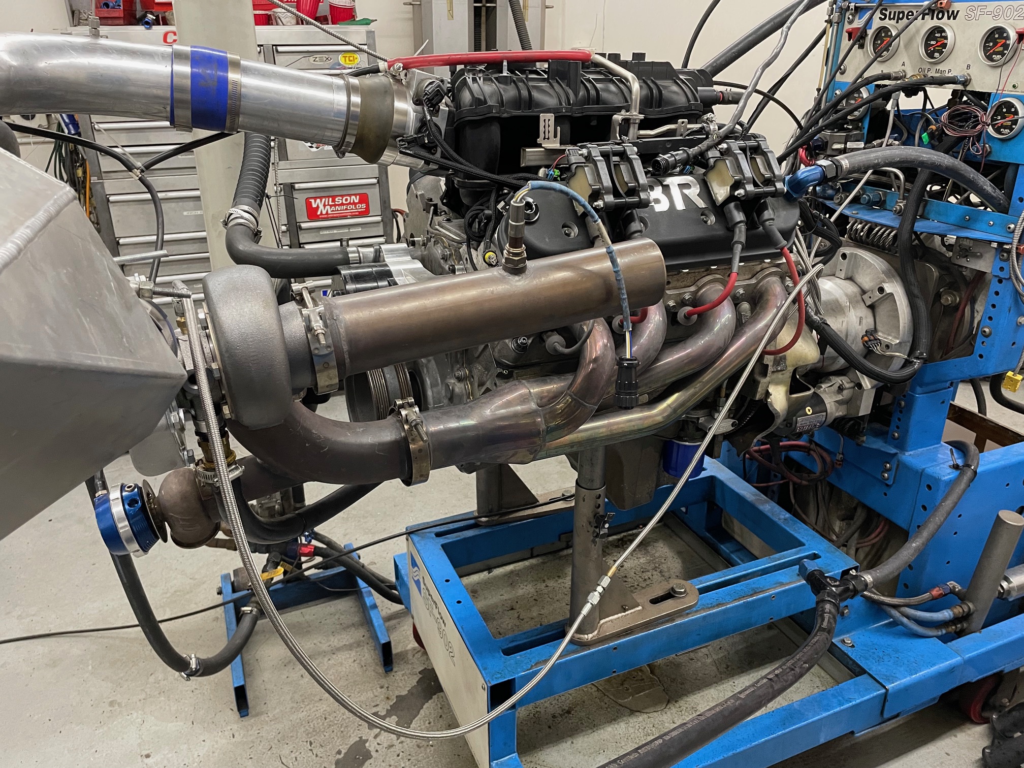
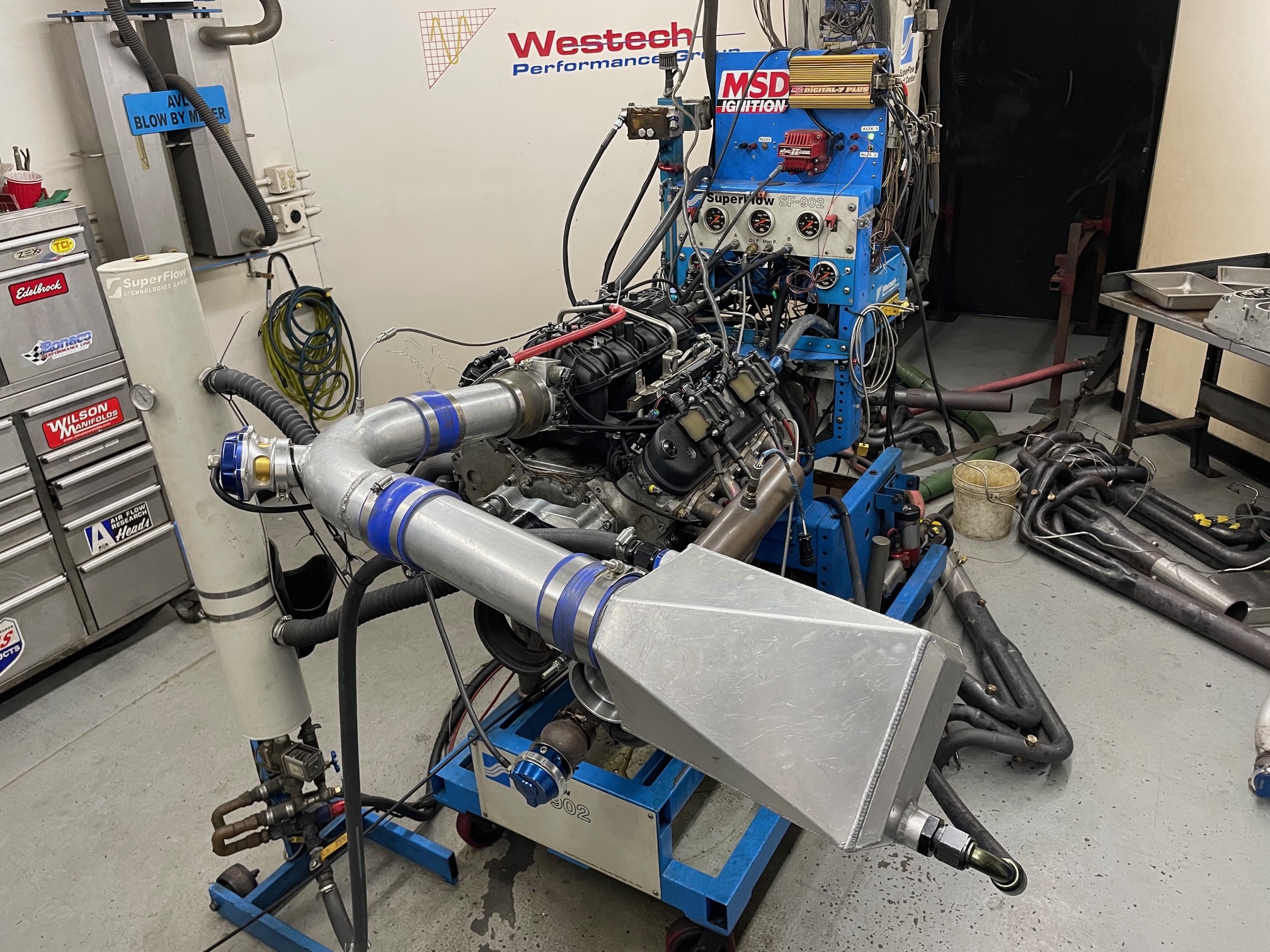
To facilitate this, we set up a unique system by feeding the turbo with only 1 side of the engine. Fear not, this asymmetrical design has been used in production vehicles (by Saab on a V6). Feeding the turbo with only ½ the exhaust flow meant the manifold would play a bigger part in response rate.

For those having a hard time understanding, all 8 cylinders were run under boost, but the turbo was only driven by the exhaust flow of half the motor (4 cylinders). The other side of the motor used a conventional header. If a normal turbo LS relies on exhaust flow from 8 cylinders and a supercharged LS relies on flow from 0 cylinders, think of this asymmetrical system as simply being between these two. The concept is not unlike using half of the motor to feed each turbo on a twin turbo set up! Trust us, it works, and the set up allowed us to isolate the effect of the different manifold designs on boost, but in no way should this stop you from making those comments.

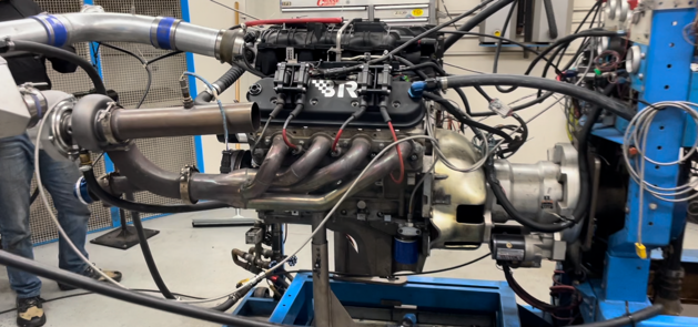
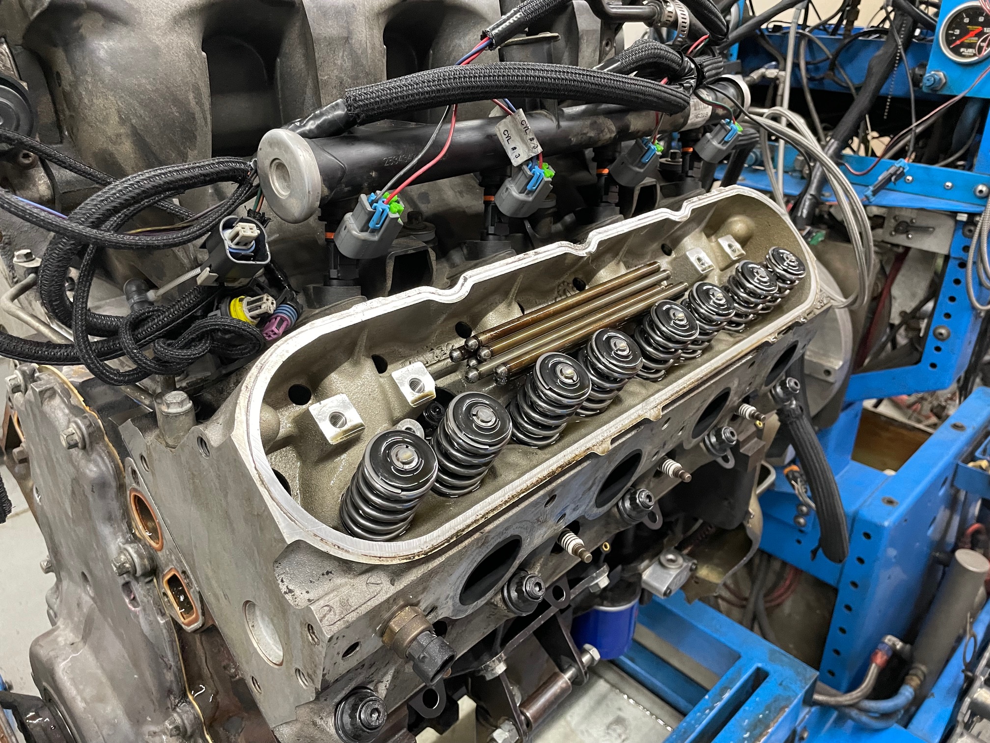
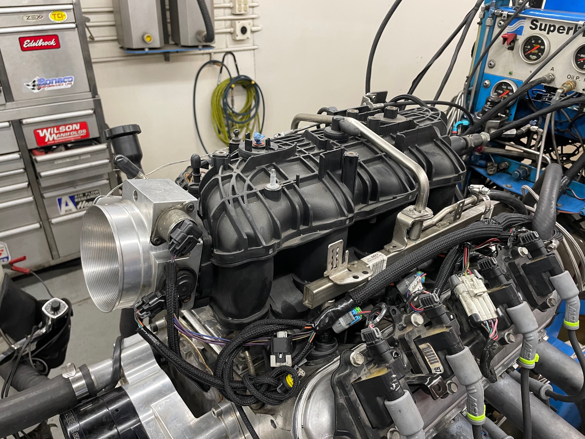
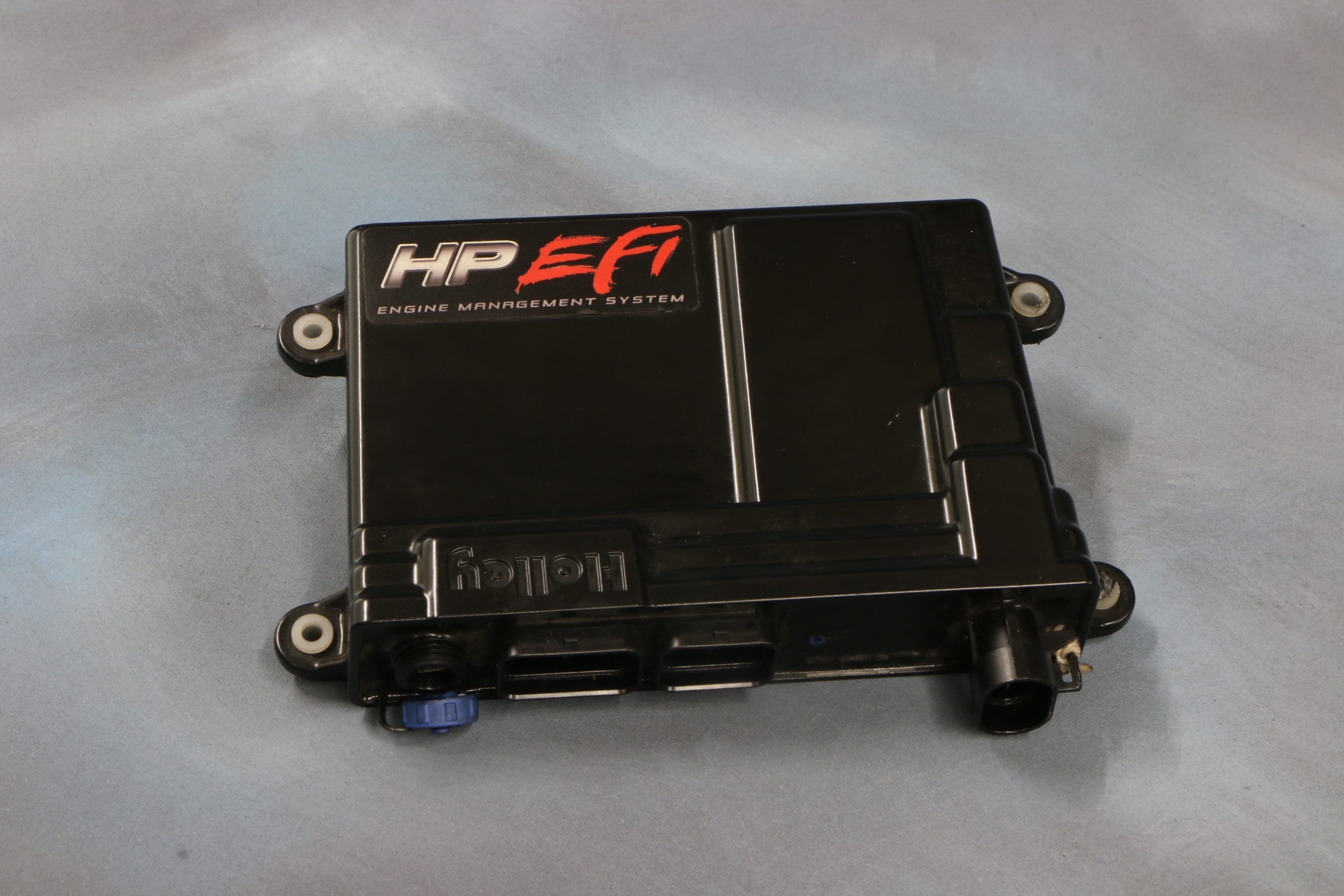
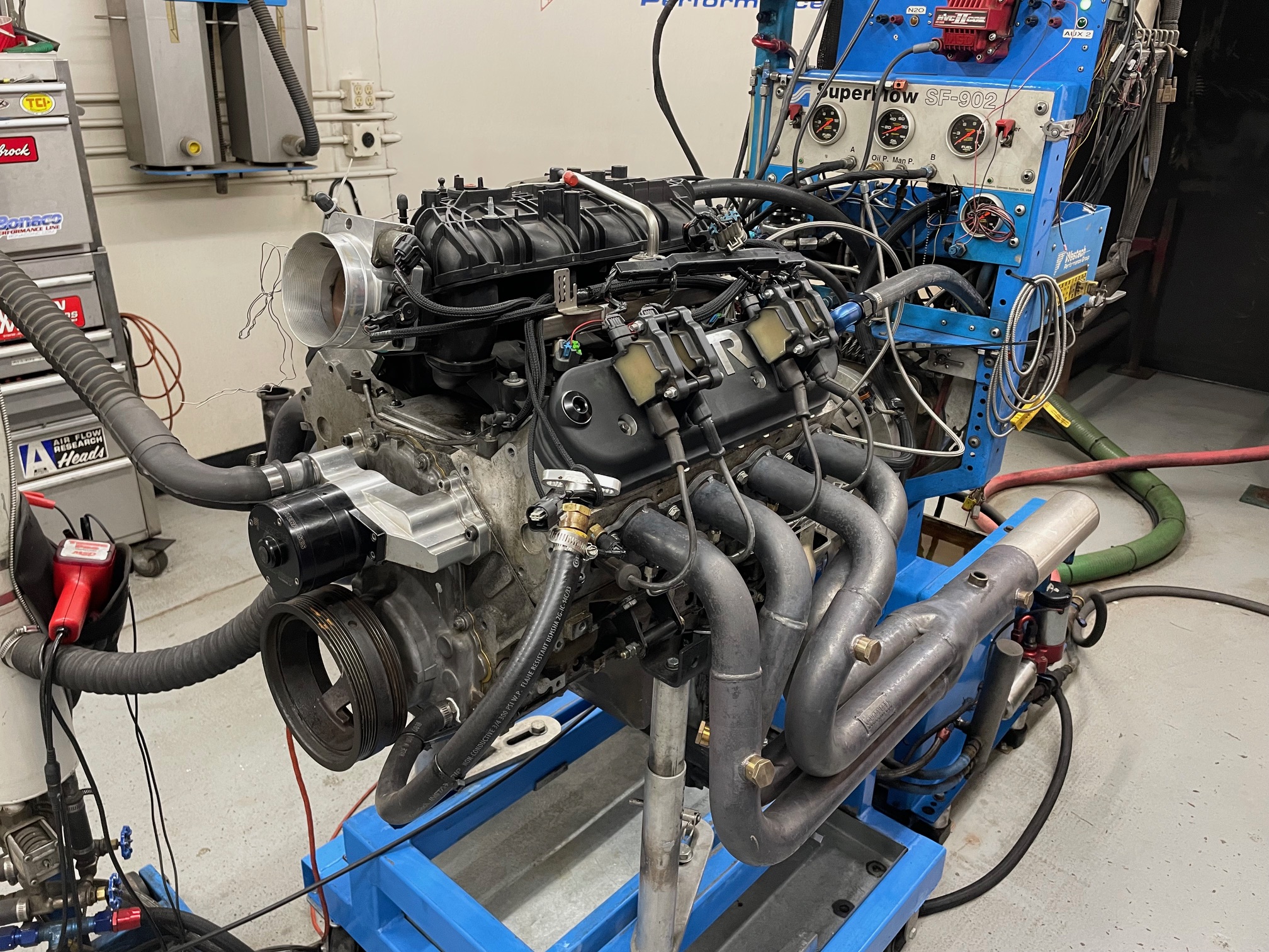
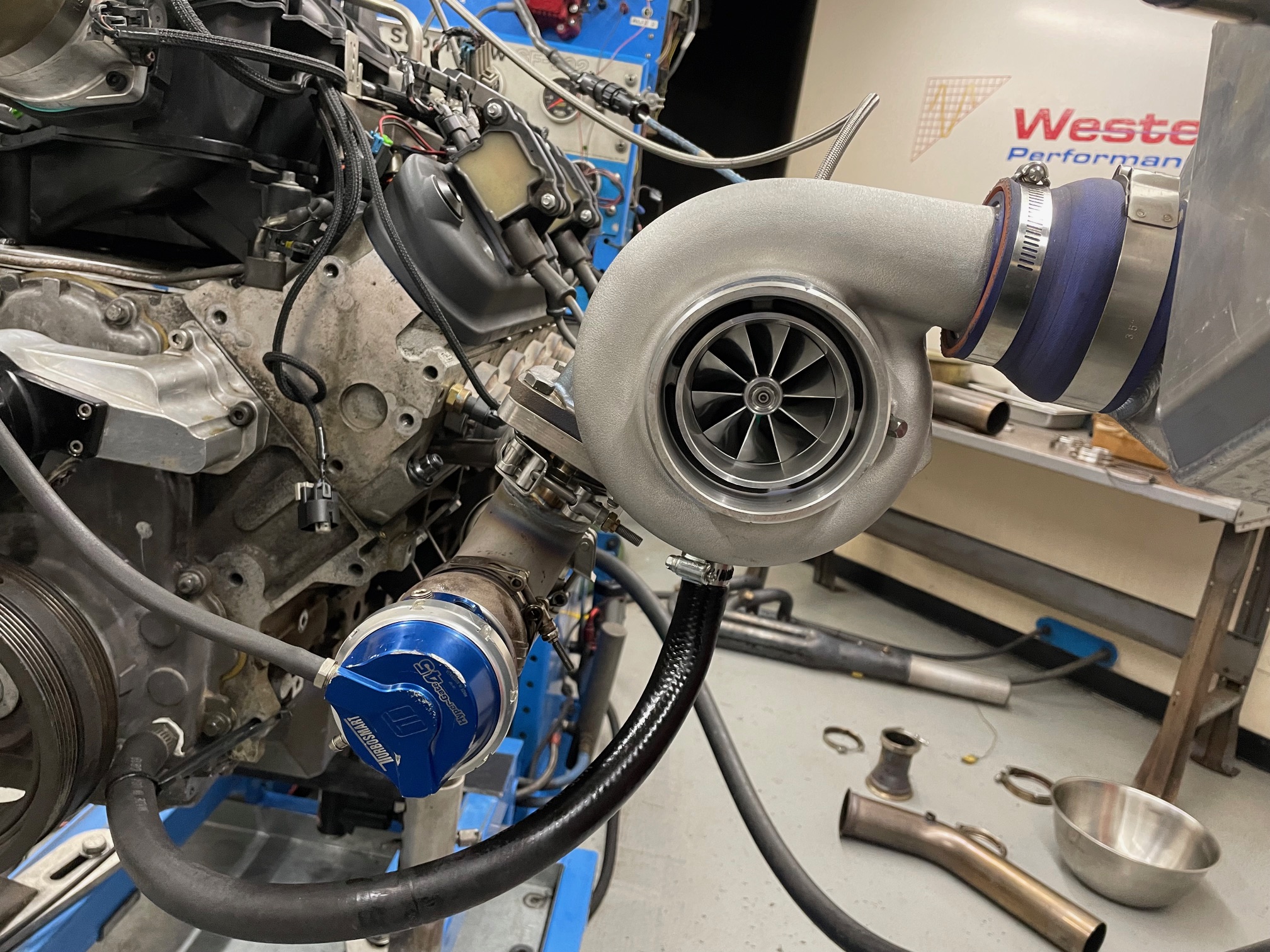
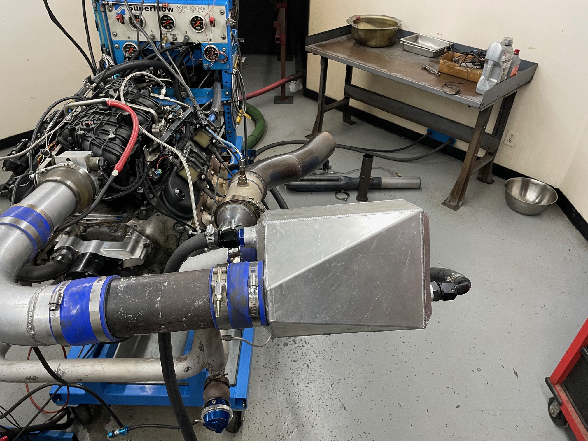
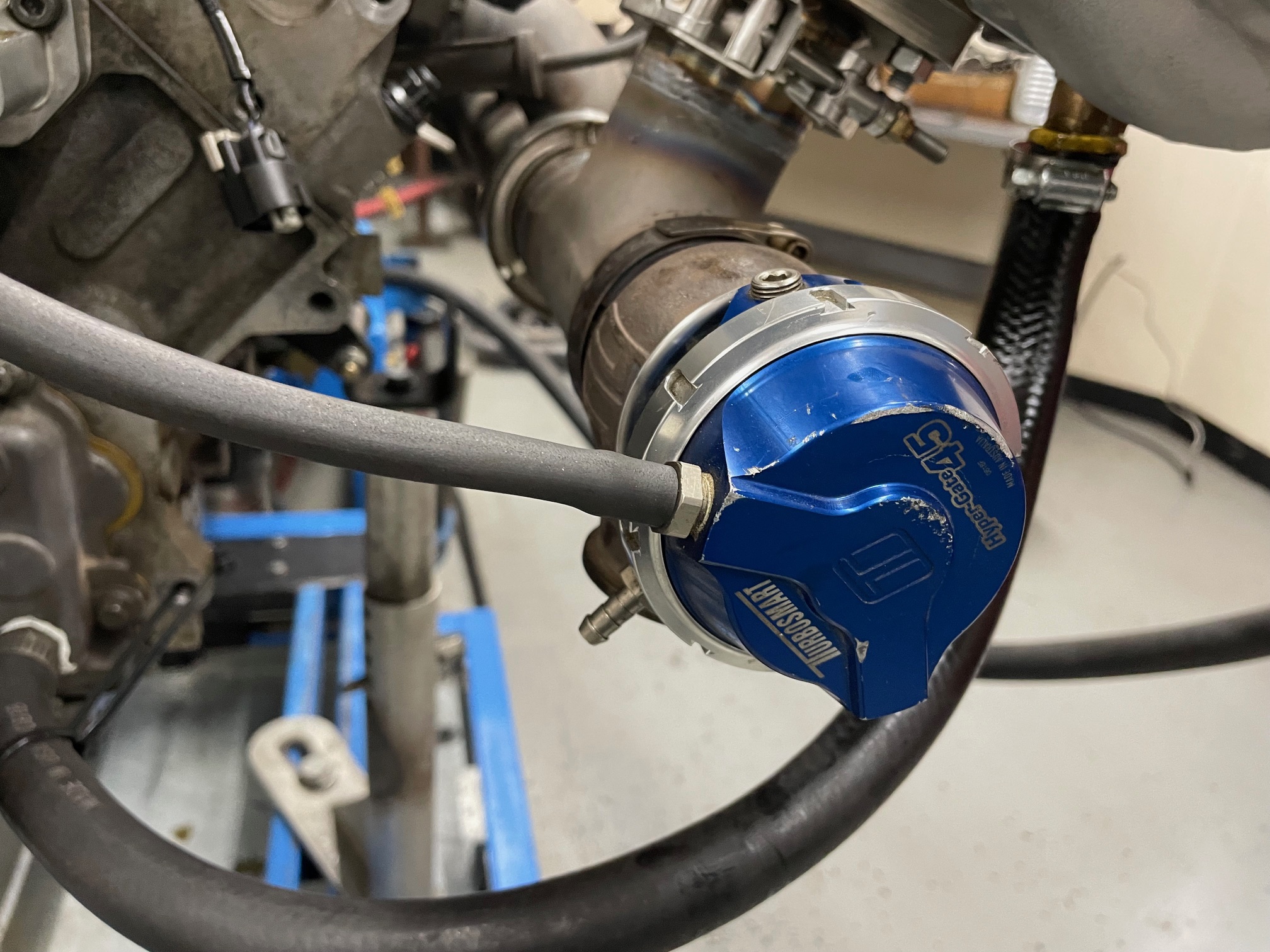
To compare the two different manifold designs, we equipped an aluminum 5.3L L33 with an RHP Low Buck Truck cam (could use hundreds of other cams as well), a TrailBlazer intake and 1,000cc injectors. All testing was run with a GTX3584RS turbo, a single Turbosmart wastegate, and Holley HP management system.

Each turbo set up ran the same air-to-water intercooler and E85 from our local pump. It is important to note that we essentially eliminated the waste as boost control by running the boost reference line to the top of the gate. The gate was closed throughout each test, meaning the asymmetrical turbo system was free to make as much power and boost as it could.

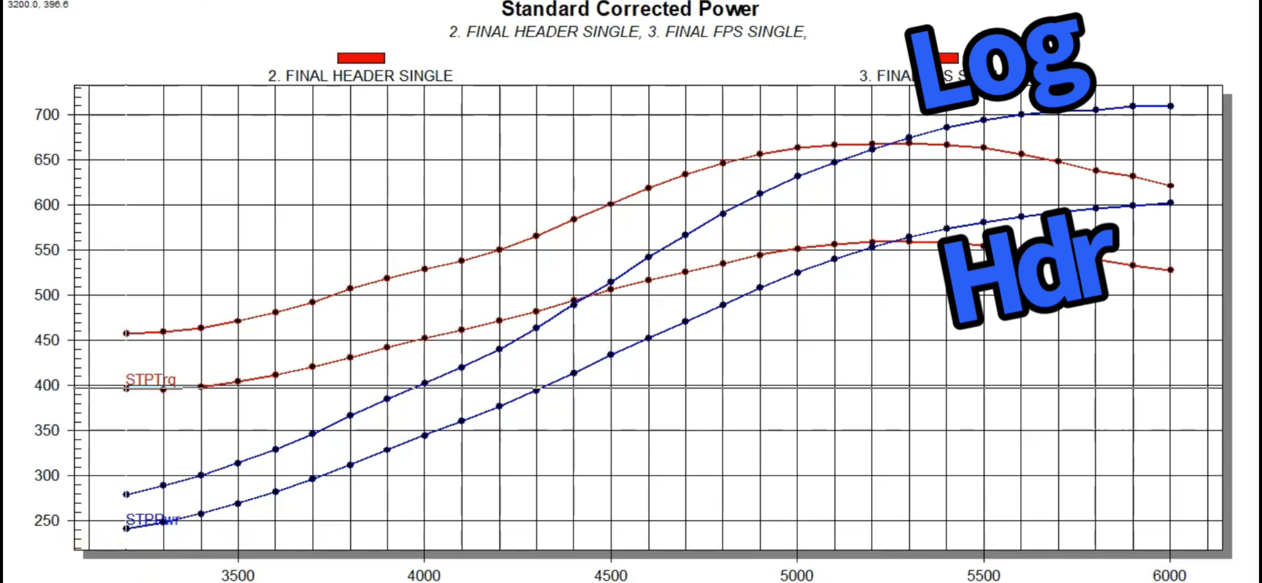
We first ran the FSP log-style manifold set up and the turbo motor responded with a rising boost curve, topping out at 175 kpa (11 psi), where the turbo 5.3L produced 710 hp and 668 lb.-ft. of torque.

We then replaced the FSP log-style manifold with a typical LS tube header (1-3/4 inch primary and 3 inch collector), using the same turbo, wastegate, and timing curve (A/F was kept at 11.5:1). Run with the larger tube header, the boost response was down from bottom to top, peaking at just 146 kpa (6.7 psi). This resulted in just 603 hp and 560 lb.-ft. of torque.

For boost response, the smaller log-style is tough to beat, but for max (4-digit) power, the tube header would likely still get the nod.

log header dyno test comparison chart
This test was designed to illustrate the difference in response rate of a tube header vs. a log-style manifold on the turbo LS. For the max-effort combo, we might opt for the header, but for response rate (typical street/strip motor), the log style is hard to beat. The GTX3584RS turboed L33 was first run with the FSP log-style manifold and the closed wastegate. Under these conditions, the single-sided turbo system produced a rising boost curve that peaked at 175 kpa (near 11 psi). The result was 710 hp and 668 lb.-ft. of torque. After running the log-style-we replaced it with the tube header. There was no change to the timing curve or AF curve (11.5:1). Run with the bigger, less-responsive tube header, boost from the turbo LS peaked at just 146 kpa (6.7 psi). The rising boost curve started and ended much lower than the log-style manifold, and produced just 603 hp and 560 lb.-ft. of torque. (Dyno Chart/Richard Holdener)
5.3L Casting Mark on an LS Engine Block
The test mule was a high-mileage, all-aluminum 5.3L L33 plucked from the local junkyard. The motor was opened up to check for the necessary ring gap. (Image/Richard Holdener)
799 casting mark on a set of LS cylinder heads
The aluminum L33 motor came factory equipped with flat-top pistons and high-flow, 799 cathedral-port heads. (Image/Richard Holdener)
man holding a camshaft
For this manifold test, we equipped the L33 with a Low Buck Truck cam from RichardHoldenerPerformance.com (RHP). Truth be told, any milder truck-style cam from Summit Racing, BTR, or Texas Speed would provide similar results. (Image/Richard Holdener)
ls engine cylinder head with pushrods and rockers removed
To allow us to run the Low Buck Truck cam, we equipped the 799 heads with a 0.625″ lift spring upgrade from BTR. These springs were chosen to allow even larger cam profiles for future testing. (Image/Richard Holdener)
close up of ls engine fuel injector
To ensure adequate fuel flow under boost (including E85 use), we equipped the turbo test motor with a set of FIC 1,000cc injectors. (Image/Richard Holdener)
headers on an ls engine during dyno test
Prior to our turbo manifold test, we ran the cammed 5.3L in NA trim. Run in NA trim (and on one side of the motor under boost), we equipped the L33 5.3L with a set of 1-7/8 inch, long tube (dyno) headers and collector extensions. (Image/Richard Holdener)
TBSS intake manifold on an LS engine
The L33 originally came with an early truck intake, but we recently installed a TBSS intake and 92mm FAST throttle body. The early truck intake would work just as well on the turbo motor. (Image/Richard Holdener)
holley HP EFI engine control module
The 1,000cc injectors were controlled by the Holley HP management system. The motor made best NA power at 30 degrees (at the HP Peak) and 20 degrees under boost. (Image/Richard Holdener)
ignition coils mounted on LS engine valve covers
For boost, even up to 30 psi, we like the factory LS3 coils (with 4.5 ms dwell) and plugs gapped at .019. We also liked the coil mounts on the BTR aluminum valve covers that facilitated removal without tampering with the coils. (Image/Richard Holdener)
ls engine running on a dyno
Run on the dyno in naturally aspirated trim, the cammed 5.3L produced 436 hp and 422 lb.-ft. of torque. (Image/Richard Holdener)
turbocharger on an ls engine during dyno test
To test the response rate of the single-sided turbo LS, we chose an 800 hp+ GTX 3584RS turbo from RHP. (Image/Richard Holdener)
water-to-air intercooler on an ls dyno test
To minimize the inlet air temp, we employed this air-to-water intercooler (running dyno water). E85 also helped keep the combo plenty safe at the low boost levels run during the test. (Image/Richard Holdener)
close up of turbosmart hypergate wastegate
Both the FSP and tube header were run with the same Turbosmart wastegate equipped with a 7 psi spring. The boost reference line was run to the top (let’s party side) of the gate to keep it closed! (Image/Richard Holdener)
fabricated ls turbo exhaust manifold.
The 2.5 inch exit FSP log-style manifold was both shorter and smaller diameter than the 3.0 inch tube header. (Image/Richard Holdener)
turbo flange on an exhaust manifold
The FSP system also featured this modular T-section that bolted to the manifold, turbo, and wastegate. It could also be used to run a traditional single or twin system with the other manifold. (Image/Richard Holdener)
turbocharger setup with intercooler on ls engine dyno test
Run on the dyno, the FSP log-style manifold produced a rising boost curve, peaking at 175 kpa and 710 hp! (Image/Richard Holdener)
turbo dyno test with ls engine
Next up was the tube header. This no-name one is common in the LS market, though Hooker has a much better version now with improved access to plugs and wires (without burning). (Image/Richard Holdener)
ls engine during a dyno test run
Run on the dyno in the same manner (turbo, tune, exhaust etc..), the header was much less responsive than the log-style manifold. Despite the closed wastegate, the reduced response rate of the header limited peak boost to 146 kpa and power to just 603 hp. (Image/Richard Holdener)

Keywords
Share this Article

Richard Holdener is a technical editor with over 25 years of hands-on experience in the automotive industry. He's authored several books on performance engine building and written numerous articles for publications like Hot Rod, Car Craft, Super Chevy, Power & Performance, GM High Tech, and many others.