Editor’s Note: Perhaps the only things Travis Jones loves more than his 1986 Monte Carlo SS are autocross courses and a good challenge. That’s why Travis is on a mission to transform his Monte Carlo from an underpowered, ill-handling daily driver to an Autocross hero. A self-described “GM guy through-and-through,” Travis is a regular on the site OppositeLock, has documented his project on his Instagram page (@sslow6.0), and will give us a first-person account of his build here as a guest writer.
Travis has owned the Monte Carlo since high school. Although he’s thought about selling it from time-to-time, Travis has held on to it for sentimental reasons, even though the car has often sat idle. After his girlfriend inspired him to try Autocross for the first time, Travis started to look at the Monte in a whole different way.
“I became obsessed with taking a 1980s boat and making it handle,” Travis said.
In Part 10 of his Monte Makeover series, Jones is tweaking the Monte’s rear suspension. You can see all the other installments of the Monte Makeover series here.
***
So you’ve spent thousands of dollars trying to get your G-body to handle and you still aren’t happy with corner exit traction? So was I. I decided to think outside of the box for a bit instead of looking at what was already on the shelf because I had every part from the shelf installed on the car and it still wasn’t working for me. Don’t get me wrong, there are lots of good parts from QA1, UMI, and the like, but even the best bolt-on parts can’t overcome a poor factory suspension design.
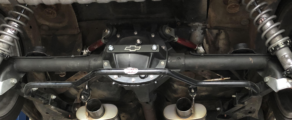
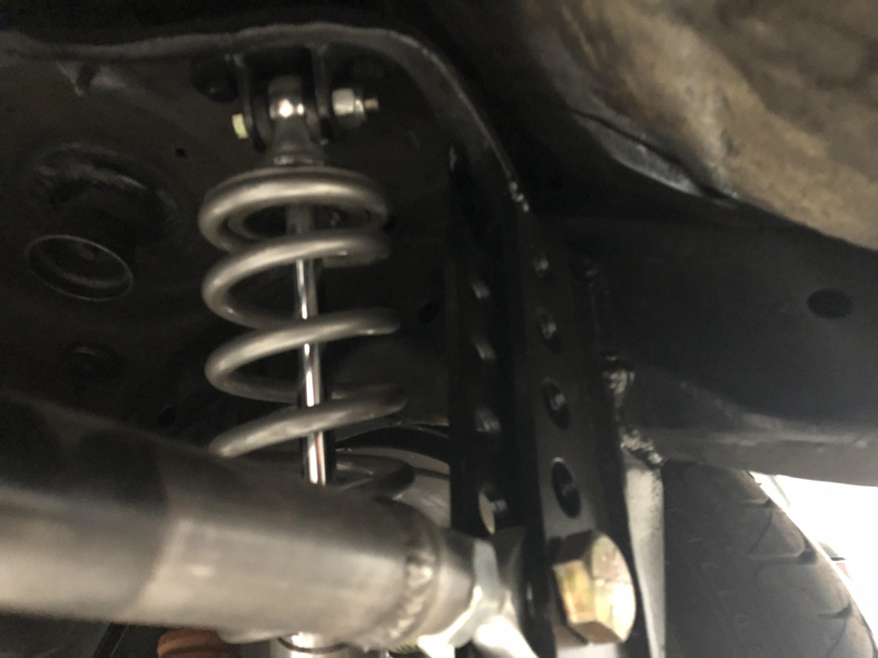
We can start by recapping what the rear suspension looks like on my car before I tore into it. At first, I had the full QA1 Level 3 system on my car, which consists of QA1 double Adjustable Coilovers with 220 lb. springs, QA1 Lower trailing arms with poly graphite bushings, QA1 Adjustable Upper Trailing Arms with roto-joints on the frame side, and poly bushings in the housing, along with their adjustable sway bar. After a while, I swapped out the QA1 Lower trailing arms for UMI trailing arms with roto-joints on each end, in search of even more articulation and less suspension bind. In addition to that, I was still using a factory 7.5 inch 10 bolt housing with a Torsen T-2 differential, Moser 28 spline axles, and a die-cast Proform girdle cover.
Now I knew that I was living on borrowed time with the 7.5 10 bolt when I dynoed the car and it made 420 hp/410 ft.-lbs. at the rear wheels. Then I installed a manual transmission, which meant I was living on borrowed time to be paid back with interest if I drove the car too aggressively. So part of the rear suspension upgrade would be a stronger rear axle too, if for nothing else than ensuring I didn’t end up on the side of the highway, watching my wheel and axle roll down the median…again.
So what rear end to go with? 8.5 G-body ten bolt? Maybe, they’re rarer than hen’s teeth these days and they still need some upgrades to be capable, Disc brakes, a helical gear-type LSD, and maybe aftermarket axles. They’re still set up for the factory suspension links though, the classic GM triangulated four link, no improvement to the geometry. 12 Bolt? No, custom 12 bolts are more expensive than a custom Ford 9 inch, and there is a smaller aftermarket for them. A Ford 9 inch is nice, but custom ones with disc brakes get spendy in a hurry, plus cast iron center section Ford 9s are heavy and not the most efficient gearset in the universe.
I ended up choosing a Ford 8.8. They are durable, have probably the most aftermarket support next to the Ford 9 inch, and are a bit more efficient and lighter than the Ford 9. From the durability side of things, an 8.8 has almost the same ring gear diameter of a 12 bolt. But which configuration of the 8.8? A Fox Body 8.8 with a few conversion parts is almost a direct bolt-in for a G-body, but once again, you’re stuck with the Triangulated 4 link geometry. Plus you need new GM bolt pattern axles and disc brakes. The Crown Vic has a very interesting rear suspension with a parallel four link and an integral watts link for centering the rear, but I’m not sure this would package well on a G-body. So what rear end would improve the suspension geometry and provide the durability necessary?
The 8.8 out of an S197 chassis code Mustang which ran from 2005-13.
When it launched in 2005, this generation of Mustang was lauded for its retro-styling and derided for its use of a solid rear axle instead of an IRS like you’d find on the Pontiac GTO, Cadillac CTS, Charger, and the soon to be launched Challenger and 5th generation Camaro.
But Ford knew what they were doing, they were able to save cost and weight to provide a competent pony car. In later versions like the 2012-13 Boss 302 Mustang, it even worked around a race track. When Car and Driver compiled their list of “Lightning Lap” times around VIR, the Boss 302 Laguna Seca was the fastest live axle car they have ever tested. Faster than a 2012 Porsche Cayman R, and faster even than its IRS equipped cross-town rivals, the Camaro SS and Challenger. Surprisingly even faster than the new IRS equipped 2015 Mustang GT.
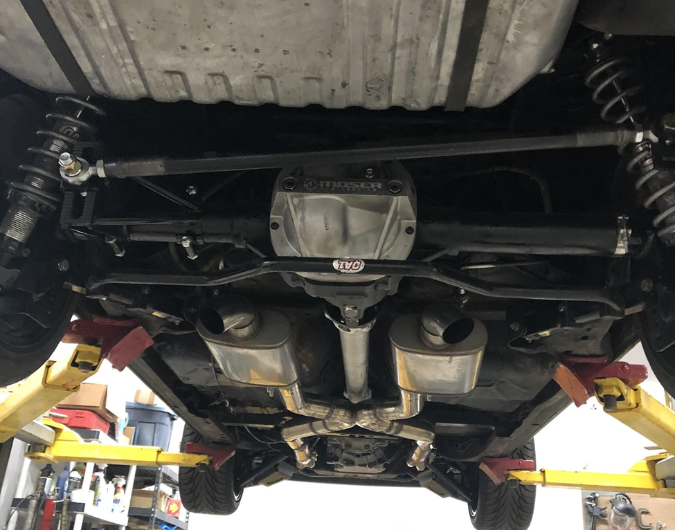
The Mustang uses what is called a 3-link rear suspension, with a Panhard bar keeping the rear centered.
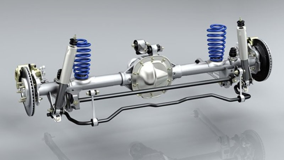
See the Mustang three-link has the two lower arms mounted perpendicular to the axle at 90 degrees.
The G-body uses lower control arms that angle in towards the centerline of the vehicle.
Without performing major surgery on the frame of my car I would have to keep the lower control arms at that angle, one of the compromises I had to make in this install. The other compromise was one that Ford made when packaging this suspension into the Mustang, the very short 8.5 inch third link. This short third link if not adjusted properly will throw the suspension geometry into disarray if the car is lowered or raised, and will cause rather dramatic changes in pinion angle at the extremes of travel. But, if it worked in the Mustang, It can work in a G-body.
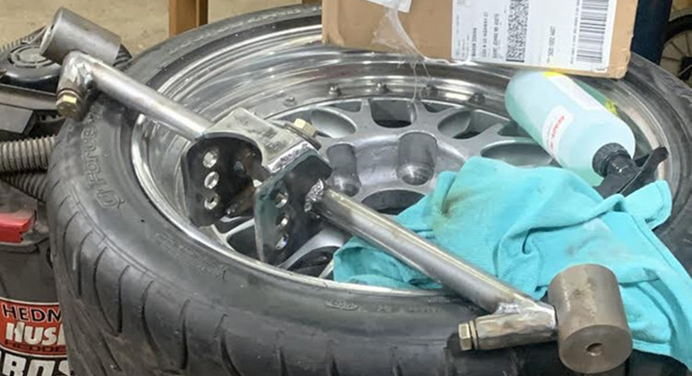
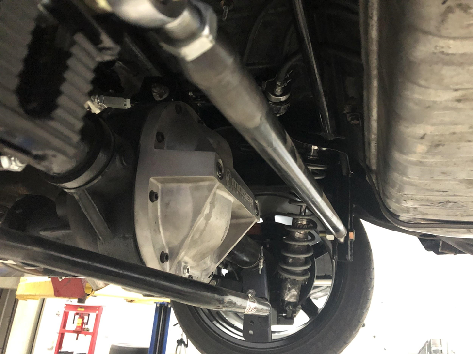
The next thing I did was find a donor axle. I found a complete rear axle out of a wrecked 2013 Mustang GT that someone had already pulled the 5.0L Coyote V8 out of for a swap into a Fox Body. I was able to purchase mine for around $300. The Mustang GT rear ends come with 11.8 inch single piston disc brakes and a 31 spline Ford Trac-Lok Limited Slip differential. Plus I was able to get all of the links, so those are some nice “freebies” that came with it. Though I ended up purchasing an adjustable UMI upper control arm for the 3rd link (UPI-1062-B).
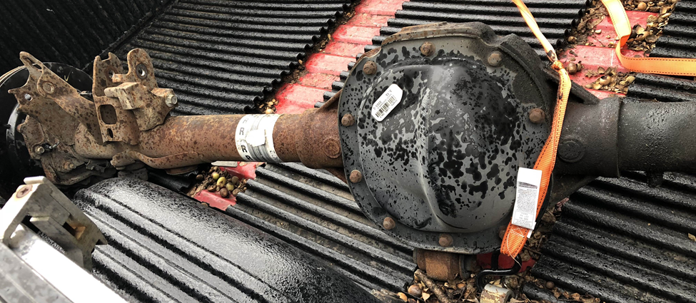
I planned on running 18×9.5 in. C5 replica wheels with a 57mm offset. Doing the math the best I could, I determined that the axle needed to be 63 inches wide. I decided I would use the Ford Factory Brakes, I just had to have the rotors redrilled for a Chevy bolt pattern. However, if you are running a standard length axle, you will want to measure to make sure that the parking brake mechanism on the back of the caliper clears the frame, and possibly swap the backing plates side to side, moving the calipers to the rear of the axle. I would have plenty of space with my 63 inch wide rear axle.
Because I decided to use the factory lower control arm mounting points, I needed to have some way to attach them to the axle. Through my partnership with Summit Racing, they sent a few parts I would need. The Allstar Performance GM Metric Chassis Trailing Arm Bracket Kit (AAF-ALL60054) had some nice multi-hole lower control arm brackets included in the Kit.
Knowing the overall dimensions that I needed, I took the disassembled rear axle housing with all of the factory brackets cut off to Drivetrain Specialists in Warren, Michigan. I spoke with Claude, one of their senior staff members about my goals for the build and how I would use it, and he recommended a few things.
His first recommendation was an Eaton Truetrac Differential instead of the factory Ford piece. It’s a gear-driven Limited Slip so it doesn’t have any clutches to wear out or fail like the factory Ford piece, second, it has what’s called a torque bias ratio of about three to one, meaning the tire with the most traction can be sent up to three times the torque as the tire with less traction. It can even help push the car through corners, and it also helps keep the car straight on launch. I was debating putting a Torsen T-2R in the car, but Claude said that while the Eaton unit doesn’t quite have the TBR of a Torsen T-2R, it is a much more durable unit, plus it was about $200 cheaper. So I decided to go with the Eaton unit.
Claude’s second recommendation was about safety. He recommended that for road racing and autocross use that I upgrade to Ford 9 inch ends, which use a pressed on bearing and a bearing retainer to hold the axle into the housing instead of C-clips. Meaning that there are no c-clips to fall out, and even if I manage to break one of the beefy 31 spline axles, the wheel would stay on the car. Having lost an axle before due to a faulty diff and C-clip, I thanked Claude for his advice and told him that I’d go for it.
The only other measurement Claude needed was the distance for the lower control arm brackets to be welded on, which is 21 inches from the centerline of the pinion to the inside face of the mount. When you shorten a rear end, they have to cut and weld, and a good rear end shop will straighten and de-stress the housing after it is welded, if you weld after its assembled, it can warp from the heat, so it’s best to let the shop weld whatever bracketry you need onto the housing in one shot when they shorten it. Claude told me they would order custom Moser 31 spline axles and the 9 inch ends and he would let me know if they needed any other parts to make it work.
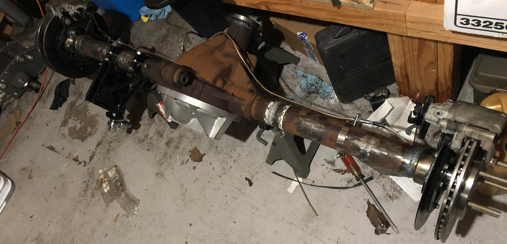
In addition to the housing and brackets, I also left an Aluminum Moser Girdle cover (MSR-7106) and a Ford Racing Ring and Pinion installation kit (FMS-M4210-B2) which Summit Racing also provided. I would re-use the Ford factory 3.15 gear, which would work well with the higher gearing of the AR5 manual transmission I have installed in my car.
After about a week and a half, I got a call from DTS that my rear end was finished. I picked it up and brought it home. I ran brake lines using clamp-on brackets and Russell universal stainless lines.
To attach the PHB to the axle I found a Keyser clamp-on PHB mount typically used by circle track racers (KYS-100-602-2) that would work, and clear the large Moser girdle cover. For the chassis side, I was a little less clear, So I picked up another part from Allstar Performance, their Weld-On Panhard Bar Bracket (AAF-ALL60168). This beefy six-hole bracket would take a lot of force, I just need to figure out where and how to mount it.
For the 3rd Link attachment to the frame, I originally had the idea of using a mount that would install into the factory upper control arm mounts that would provide the mounting points for the 3rd link. I had a friend with a plasma table make one, however once installed on the car we realized that this simply did not allow for the right amount of space to have a workable pinion angle. If I had more time and he was closer geographically I probably would have explored this idea further as a bolt-in mount would be nice. I’ll explain exactly how we eventually mounted the upper 3rd link in a little bit
For all of the work I was able to use my friend’s shop with a lift, it made the job immeasurably easier. I’m no welder so my friend’s dad did all the welding. The first step was to drop the gas tank, I knew we would be welding and gas tanks and welding sparks don’t go together very well. Next was the QA1 sway bar, four bolts and it was gone. From there we removed the main brake line to the rear steel lines, drums, pads and hardware, and the parking brake cables from the 7.5 rear end. Then two bolts for the lower shock eyes and four bolts from the upper and lower control arms and the 7.5 10 bolt was out.
The first step in assembling the rear end was to attach the lower control arms to the new 8.8. We did this by setting the 8.8 on jack stands and lowering the car on top of it. Once the rear end was attached to the LCAs we modified the QA1 shock mounts, adding a weld nut to the back, and welding them to the lower control arm brackets after verifying their position and removing the eyelets for the LCA bolts. This way the lower shock mount height was not dependent on which hole the lower control arm was in, and it turned a two wrench operation into one for the lower shock bolt.
If you’re going to modify your car, try to keep serviceability in mind.
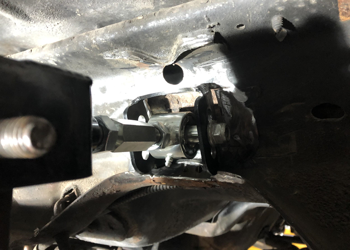
With the lower links installed and the shocks in place to hold the rear end up. We used the lift to bring the car up again. From here we mocked up the third link using the bracket my friend had made. It bolted right in and using a screw jack we were able to get it together, however, when we lowered the car to check the pinion angle, we found that the mount would have to be positioned higher because the pinion angle was way off and that the lower portion of the third-member could come into contact with the bar spanning the UCA mounts under suspension compression. No good.
So we raised the car again and removed my friend’s bracket. We decided to cut the vertical cross-bracing on the frame cross member directly behind the rear seat to gain more space for the third link. It looked like we might have enough room, but just not quite enough. From here we cut a rectangle out of the crossmember to get a little more space, we cut the three-hole mount from the box off of the bar mount that my friend had made. We mocked that up in the rectangle hole we had just cut and everything looked great.
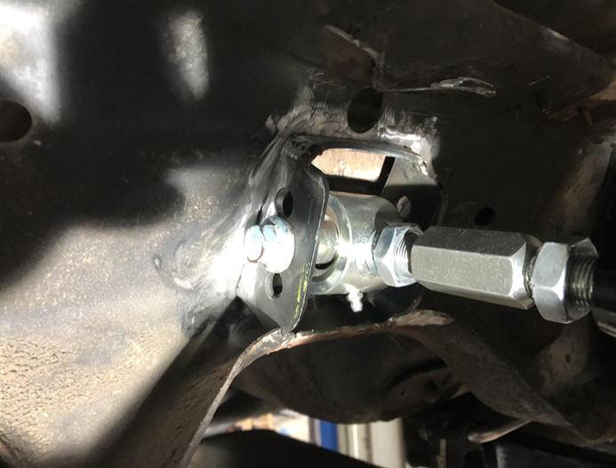
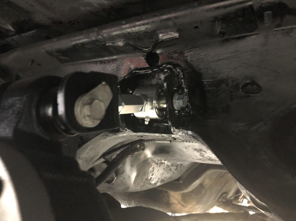
With the rear end out and the chassis side third link mount burned in, I let it cool and gave it an application of chassis black spray paint. Once that dried, we bolted the rear end back up using the 3rd link, LCAs, and shock mounts once more and put the car in the air. We bolted the clamp-on Panhard bar bracket to the axle and started to look where the best place for a Panhard rod mount would be on the chassis side. We identified the space on the frame right inline at the end of the factory spring pocket. We trimmed away part of the tail of the bracket where it attached to the frame and tacked in the Allstar 6 hole PHB mount.
We knew that we would have to support the bracket, in a three link the Panhard bar sees 100% of the lateral G-load of the weight the rear suspension carries, so it needs to be a sturdy substantial unit. We used cardboard templates and created gussets out of 1/8th inch steel. We tacked everything into place and then cut down a piece of 1-1/4 inch DOM 0.120 wall tube for the Panhard bar. We set the threaded tube ends into the tube with the rod ends threaded in and mocked everything up. It worked.
From here we just burned in the Panhard bar mount, the gussets, and attached the top of the PHB mount to the existing spring pocket on the frame to maintain the stiffness of the spring pocket. Next, my friend with the shop triple-pass TIG welded the threaded tube ends to the tube, we re-installed the rod ends and the whole PHB assembly into the car using 3/4-10 bolts and I blasted everything with more chassis black paint. Then we re-installed the QA1 Sway Bar.
The first noticeable thing is that first gear is now usable. Before, the 3.75 first gear and the 3.73 rear gear of the old 7.5 was just too short. The second thing that I noticed was that the car seemed to ride better, I’m not sure if this due to the removal of bind or a freer articulation of the rear axle, but even on bumpy Michigan roads, the car rode better than ever. The third thing it noticed was off the line traction. With a small roll out I could absolutely mash the gas and the car would just go, no fuss, no tire spin, just immediate acceleration.
Next, I hopped on the expressway to see how it felt in long sweepers (aka On/Off Ramps). The car felt planted and flat, the rear end didn’t squeal or squirm, It just took a suspension set and kept gripping as I increased throttle and speed. It felt so planted and I was approaching a high speed, so I took my foot out of it, fearing that I would find the limit unexpectedly and run out of driving talent to recover the car if it were to spin. For sure I would need some form of closed-course to find the limit in this car.
Comments