
If it ain’t broke, don’t fix it, is a common expression heard around our garages. But we say, if it’s broken, make it better. Whether it’s a replacement of a bad unit, or simply wanting more power and efficiency, a single-fire ignition is a common and easy upgrade for V-twins. We took a short afternoon to install the MSD V-Series Single-Fire ignition module on our S&S 107 c.i.d. V-twin.
Single-Fire vs. Dual-Fire
Most standard Harley-Davidson models use a dual-fire ignition, which is not sophisticated enough to separate the two cylinder’s sparks; instead, one coil fires both spark plugs at the same time, every time.
This means while it’s the proper timing on one cylinder, the other cylinder often has a wasted spark.
This wasted spark can cause backfires and efficiency losses. Those problems are compounded when you add a larger cam or carburetor. For performance V-twins a single-fire ignition is a must.
With a single-fire it only sparks on the appropriate cylinder, resulting in a more concentrated, powerful spark and a smoother idle.
Another major advantage of our MSD single-fire ignition is the optional Kick Start mode, which is a violet wire connected to the starter relay (or can remain unhooked if installed on a kick-start bike). This delays the spark when starting the bike, saving the life of a starter on a high-compression engine.
Parts List
For single-fire conversion, a single-fire coil (meaning it has two separate coils built into one unit) and an ignition module are necessary. On our S&S 107 c.i.d. we already had a single-fire coil, but the ACCEL Ignition brand is a quality option.
NOTE: You’ll also need to know exactly your application, Sportsters (aka small V-Twins) use a different ignition and some new models already feature single-fire ignition. One unit fits a wide range of applications, but please confirm yours before purchasing.
…
Installing the Ignition Module
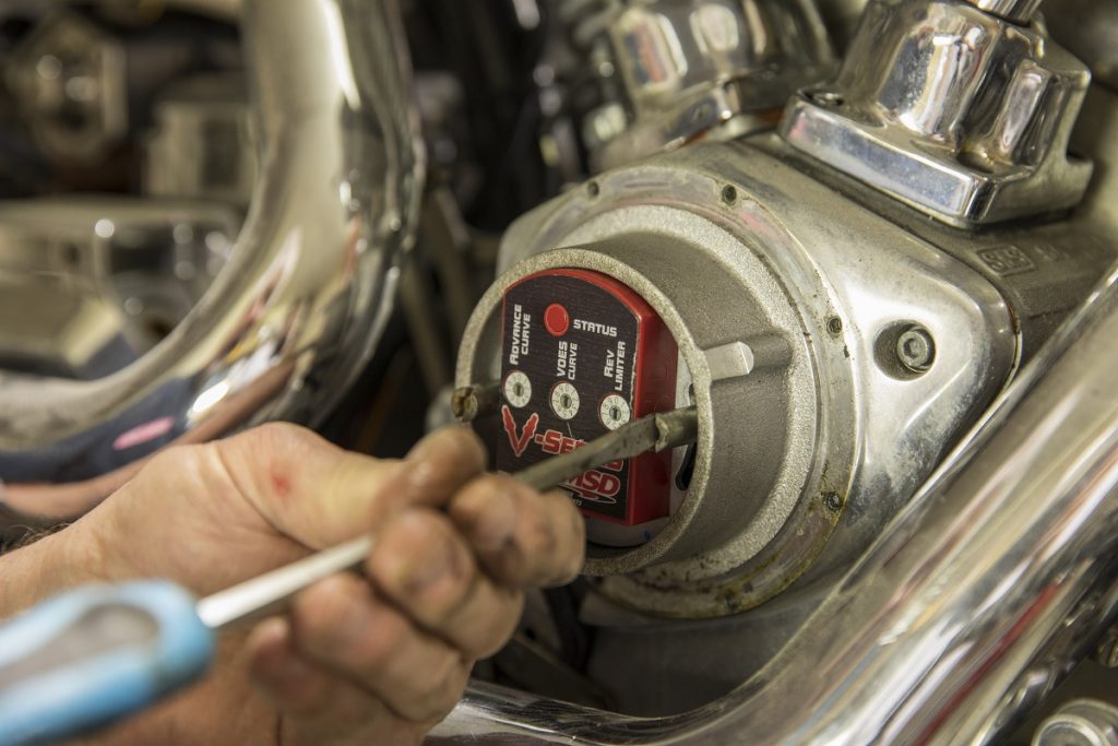
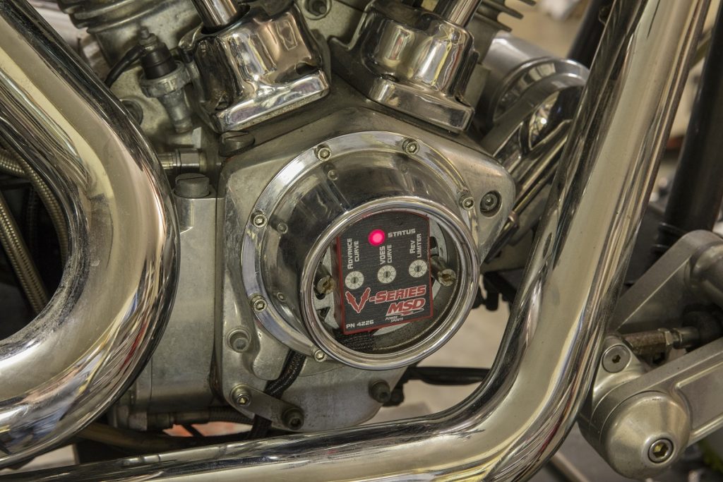
Our S&S 107 c.i.d. V-twin lays in a custom motorcycle, which experienced a surge of voltage from an overloaded jump on a bad battery. This shorted out the previous ignition module, shown by the LED indicator light not lighting up. We began by removing the two screws (typically either a screw head or small Allen bolt) that hold on the point-cover. The point cover is screwed onto two threaded posts, which are also screw in and hold the base of the ignition in place. Remove those and the module will come right out.
NOTE: It’s important to keep those two posts/screws, but unimportant where the slots of the base are, as we’ll be re-setting the static timing when we’re done.
…
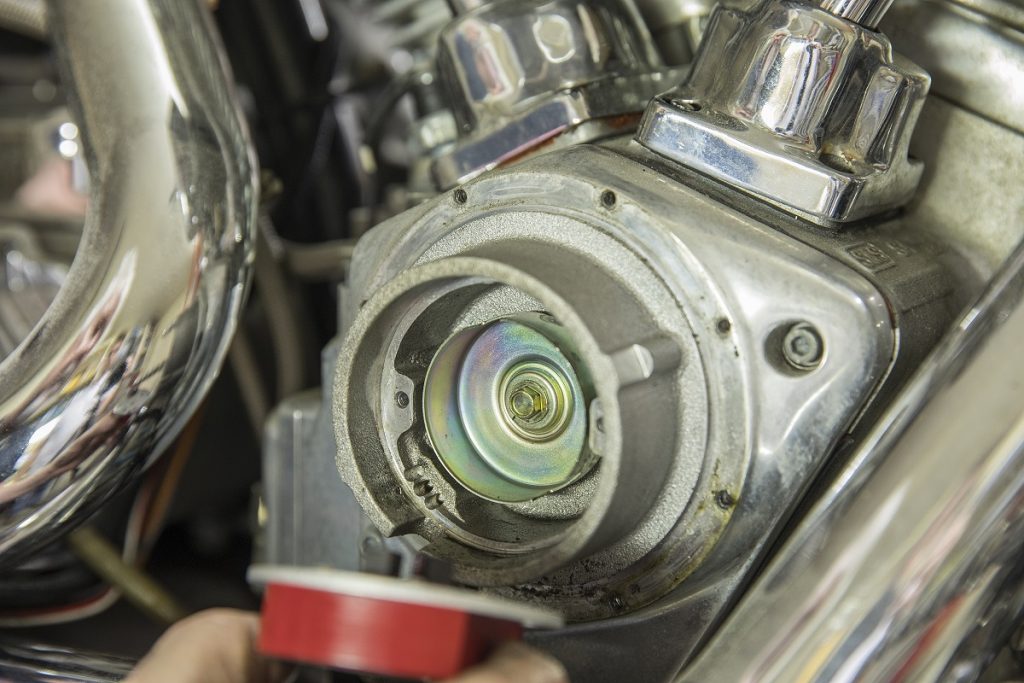
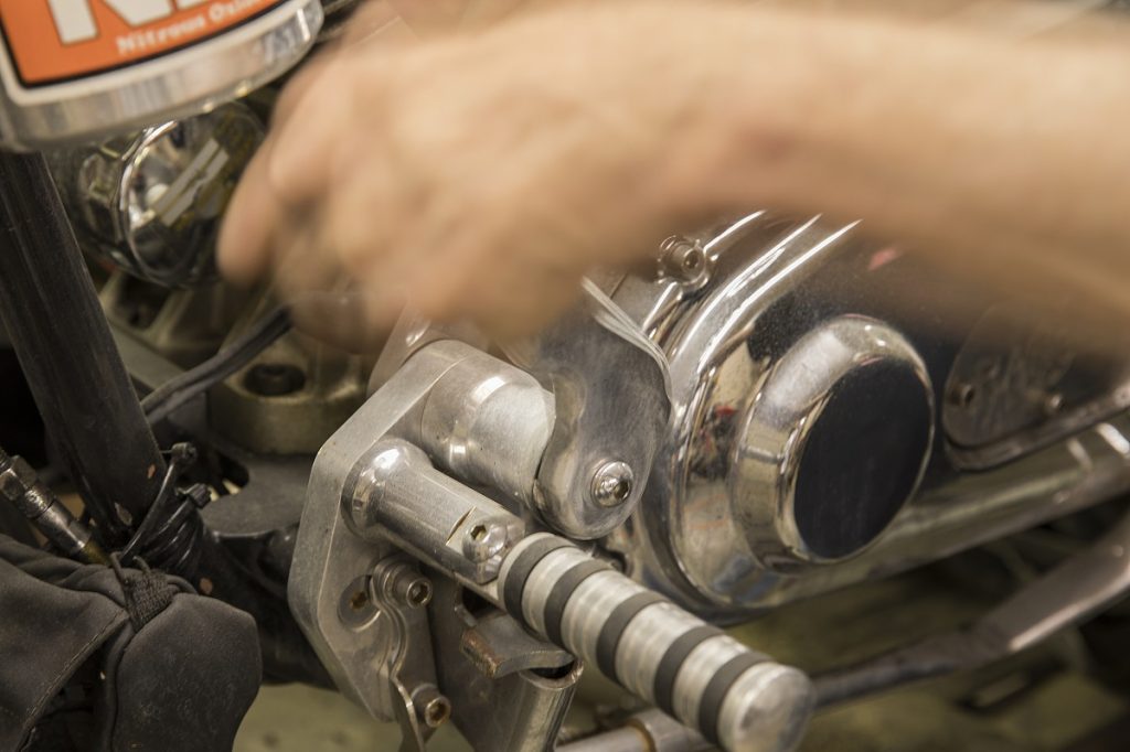
Unique to our application is the ignition wire loom tucked behind a large chrome cover. Most Harley-Davidson models don’t have this cover, do NOT get this cover confused with a cam cover. Notice our motorcycle has the cup behind the module already installed, this is important for this style ignition.
…
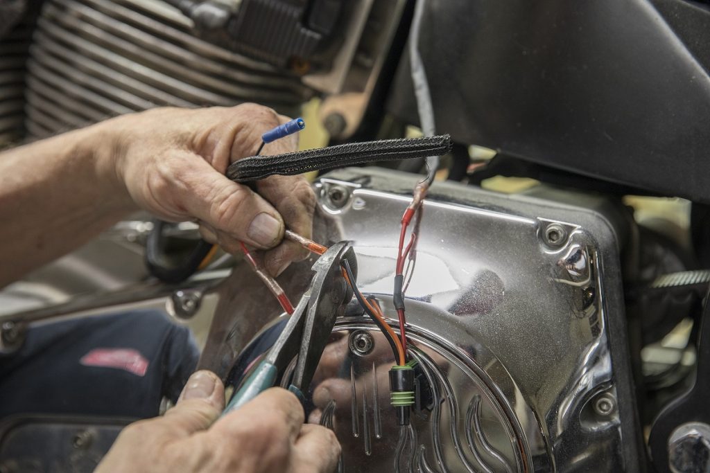
We noted how the wire loom is run in-between the engine and transmission and up the frame, then we cut it and unbolted it from the coil. If you’re unsure about the exact length you should cut yours, simply perform this step later.
…
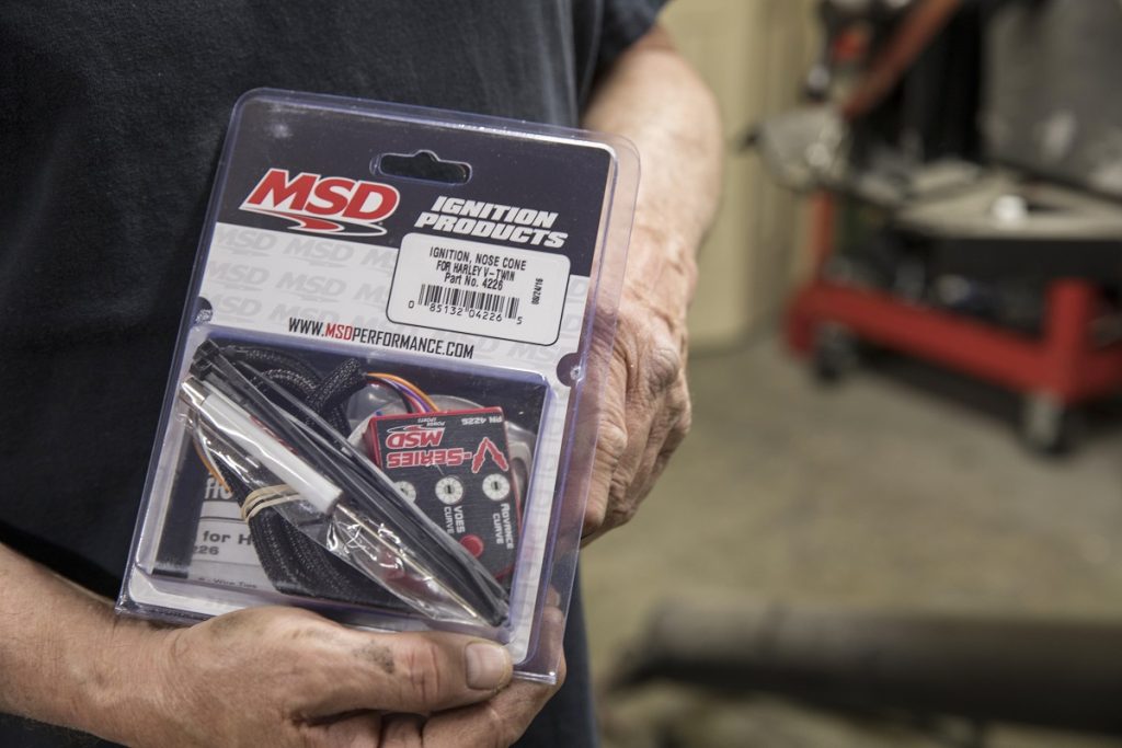
This MSD ignition module (MSD-4226) includes over two feet of wire, loom, wire ties, and a screw driver you’ll need for adjusting settings.
…
We bolt the module in place, and run the wires through the same path as before. We’ll adjust the module on the plate last, so leave the screws loose.
…
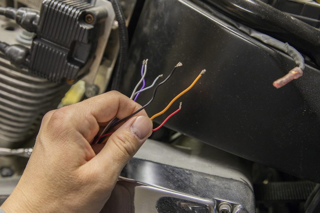
The instructions include a wiring diagram, which highlight optional items like Kick Start mode, tachometer, and VOES switch. If you lose the instructions, view them here.
- Red – Connects to switched 12 volts (coil positive)
- Orange – Connects to negative side of front cylinder coil in single fire
- Black – Connects to negative side of rear cylinder coil in single fire
- Gray – Tachometer
- White – VOES Switch
- Violet – Starter
In our application, we do not have a VOES switch or a tachometer, and therefore those wires are cut short and insulated. We want a delayed spark for our high-compression engine so we installed the violet wire.
…
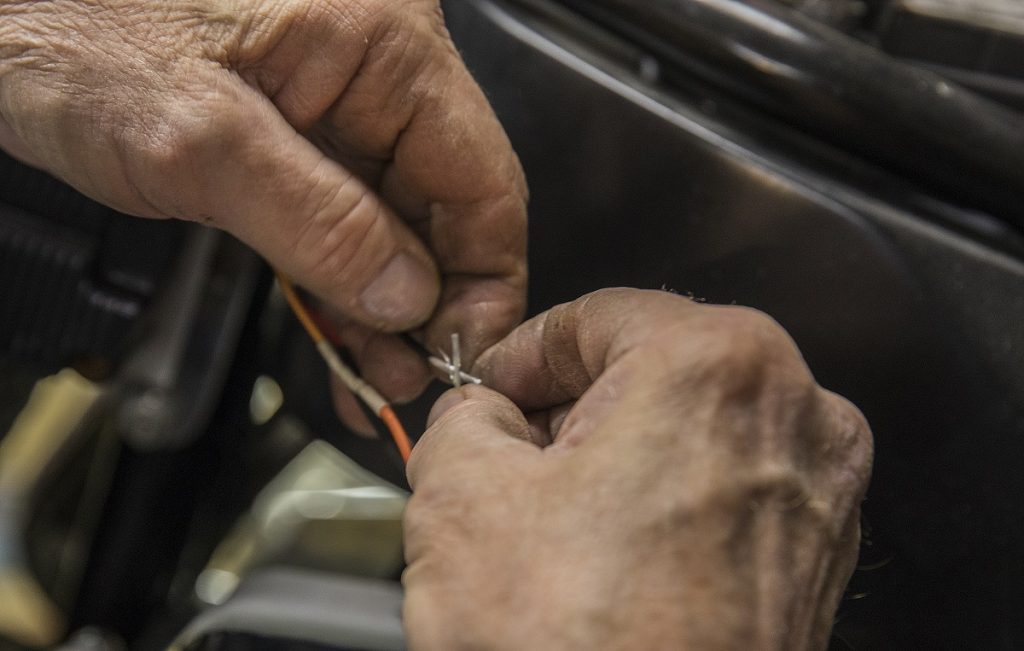
It’s important to solder the wires—don’t be that guy using household screw-wire-connections. Also, don’t forget to slide heat shrink over the wire before (included in the kit). For a quick lesson in soldering, skin the wires about 1/4-inch to 1/2-inch back. Hold those two skinned sections in an X.
…
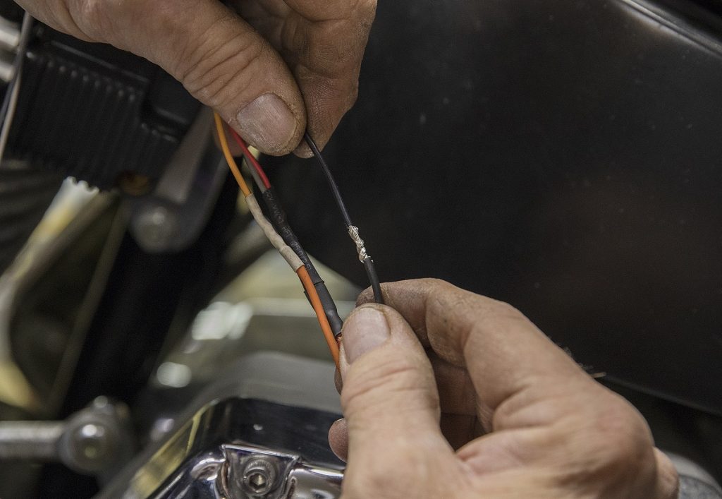
Now, twist the wires around each other and then solder.
…
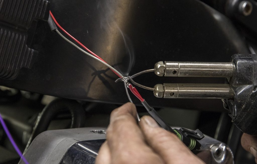
Prime the soldering tip with solder, then heat the bare wire and place the solder on the other side of the wire. The heat will eventually melt the solder and pull it into the wire towards the gun.
…
Setting the Static Timing
Now that everything is installed and the wiring is buttoned up, we set the timing.
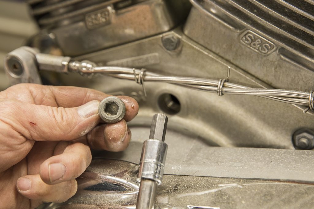
We began by removing the inspection cover 3/8-inch Allen plug on the left side of the engine case, at the base of the cylinders.
…
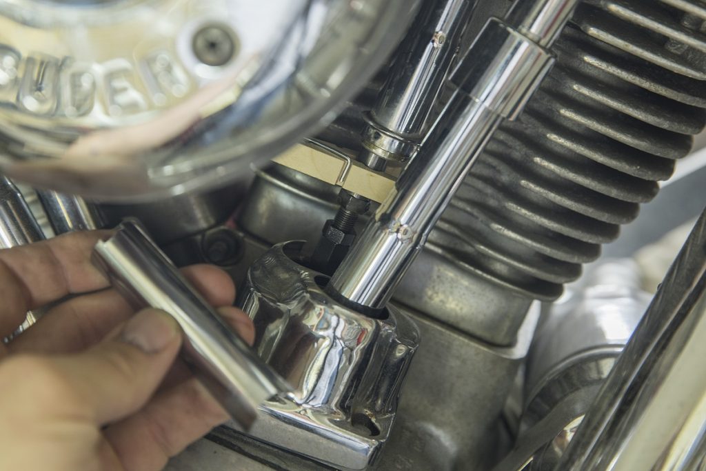
Next, find the front cylinder’s Top Dead Center (TDC). We removed the cover for the front cylinder intake pushrod. We use a clothe’s pin to hold the cover up and out of the way. This allows us to check the position of the valve in order to find TDC.
…
We removed the spark plugs and put the engine into high gear, which allows us to roll the rear tire to find TDC. This is a two-person job, with one rotating the tire in the forward direction and other finding the compression stroke by watching the push rod. When the intake pushrod goes go and then back down, you’re coming up on compression stroke.
…

Now, walk back around the engine and look for the TDC mark on the crankshaft weights. Most V-Twins use different but similar appearing marks to identify TDC. Ours reads T:F, but it’s important you verify yours before continuing as there are multiple marks on the weights. The MSD instructions are helpful to determine your exact application and placement. We then held the rear brake with a tie-down strap as the engine wants to rotate forward and fall past the mark.
…
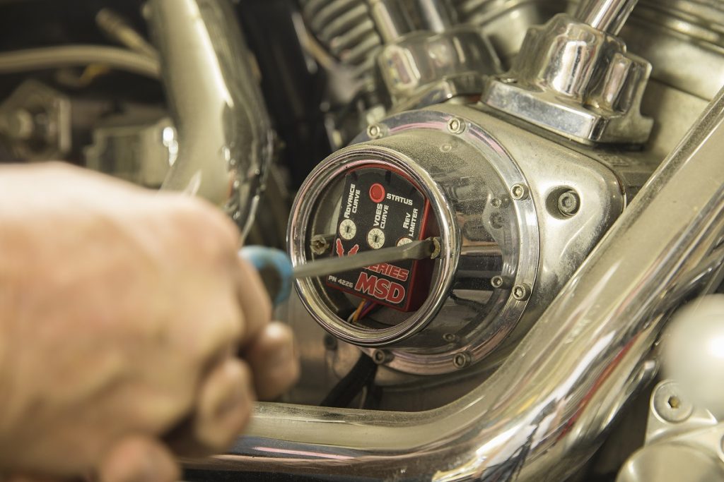
With the ignition module loosely held down and the ignition switch on, we rotate the module back and forth until we find the exact moment the LED indicator light comes on—don’t go past that point. You’ll likely have to go back and forth very slowly to find the precise moment the light comes on. Tighten the module down and do it all again. Rotate the engine, watch for TDC on the counter weight and see if the light comes on at that exact moment.
…
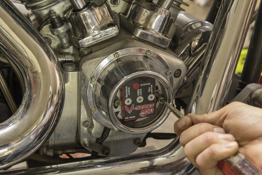
The included screw driver is helpful in selecting the settings you want. Don’t play with the VOES Curve or Advance Curve unless you know what you are doing. A major feature, like a lot of MSD modules, is the rev limiter. Set it and forget it. Now, we can put the covers back on and ride.
[…] If it ain’t broke, don’t fix it, is a common expression heard around our garages. But we say, if it’s broken, make it better. Whether it’s a replacement of a […] Read full article at http://www.onallcylinders.com […]
What have you got that will work on a Honda 688 cc Honda V twin?
Is there a single fire ignition available for panheads?
Great tutorial. I have an S&S V-96 with the factory Super Stock Ignition and S&S single fire coil. I lost all spark, and can’t find a good testing procedure. Can you Advise? Thanks
I am running hydrogen on my 85 dyna i am using a turbo set at 5psi to equally load my cylinders with Hydrogen i am using a turbo that is big so my bottom rpm its lazy and top is runnin effortless.my motor is a 1340 evo factory my carb is s&s B
I am asking do you have a aplication for a turbo
I have a revtec 100 cubic inch 2004,will it work on it?
I have 1994 heritage low milage coil went out so want to replace with ignition upgrade then sell it. Thanks for info
How much labor time ? thnx
Hi mate
I am changing from dual fire to single fire but I cannot find any information about what to do with the module.
Can you set me straight please?
Are rotor cups the same for both single & dual fire ignitions…as in can you use the rotor out of the dual & put with a single fire.