(Image/Mike Mavrigian)
Editor’s Note: Mike Mavrigian must do nothing but build engines and write stories about them. We have visions of his shop, Birchwood Automotive, set deep in the woods with Mavrigian keeping little forest creatures for friends.
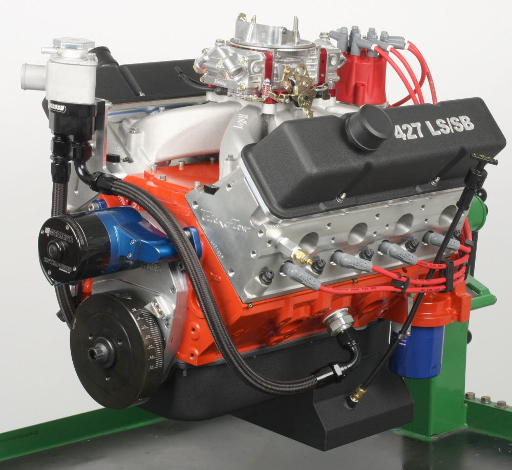
His latest engine build is a 427—well, it’s a hybrid of sorts that blends the best of the Gen 1 small block Chevy and the GM LS series engines. It’s a combination made possible by World Products’ Motown II LS block, which allows the use of free-flowing LS cylinder heads on small block Chevy architecture. In this case, the combination produced a respectable 641 horsepower at 6,300 rpm, and 555.7 foot-pounds of torque at 5,200 rpm. Now, in the first of a two-part article about this engine build, Mavrigian begins to walk us through the process.
…
The Block
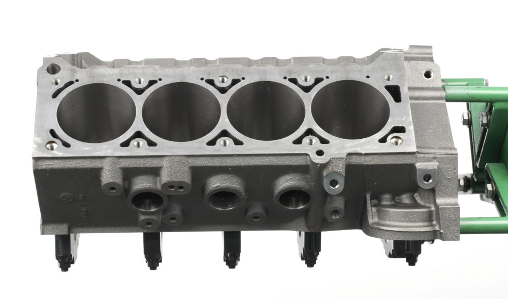
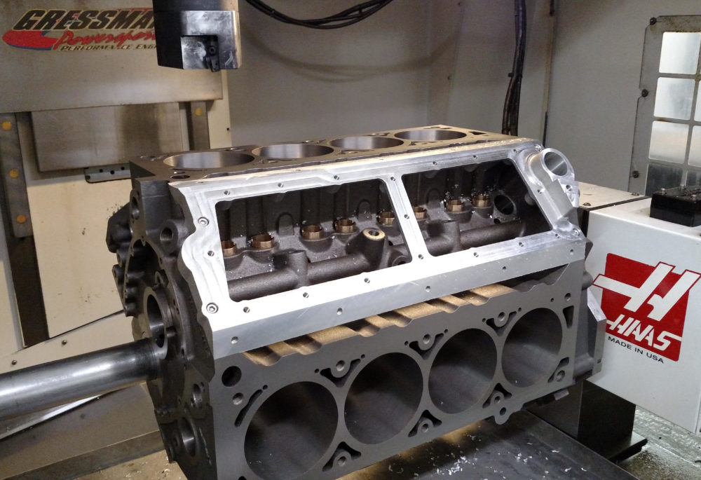
The World Products Motown II LS iron block lets you build an engine with the strength of the tried and true small block Chevy and the vastly superior breathing of LS cylinder heads. The block has LS-type cylinder head bolt locations, 9.240 inch deck height, lifter bores, and cooling passages.
The Motown II LS is an iron block with aftermarket-type upgrades like thick decks, priority main oiling, and four-bolt main caps. It’s available in five versions, all with the 9.240-inch LS deck height. The cylinders can be overbored to a maximum of 4.200 inch:
- WRL-084080: 3.995 inch raw bore, 350 nodular iron caps
- WRL-084081: 4.120 inch raw bore, 350 nodular iron caps
- WRL-084081-904: 4.120 inch raw bore, 350 nodular iron caps, .904 inch lifter bores
- WRL-084181: 4.120 inch raw bore, 350 billet caps
- WRL-084181-904: 4.120 inch raw bore, 350 billet caps, .904 inch lifter bores
The block can be ordered bushed for standard LS .842-inch roller lifters or 0.904-inch roller lifters. The lifter bores are bushed undersize and must be finished for your specific lifter diameter.
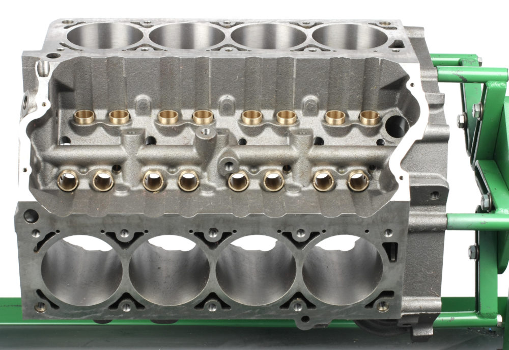
Bushed lifter bores are standard and must be final-machined to accommodate either .847″ or .904″ diameter lifters.
The Motown II has .600-inch thick decks and beefy .250-inch thick cylinder walls. The block follows traditional small block Chevy design except for the .134-inch raised cam tunnel for added stroker clearance, the use of 55mm cam bearings, the deck configuration for LS heads, and lifter bore spacing to accommodate the LS valvetrain. Aside from the metric rocker arm and intake manifold bolts, all threaded fasteners are SAE.
Since the block has the Gen 1 crankcase design, windage control and crankcase bay-to-bay breathing is vastly improved over the factory LS Y-block design.
Due to the LS lifter bore spacing, a special camshaft is required.
Currently, the cams are only available from Erson and COMP Cams, and must be special-ordered to your specifications.
You can run a distributor on the Motown block using the World Products aluminum valley cover with a distributor mounting boss.
If you’re running electronic fuel injection and don’t need a distributor, World offers an oil pump drive assembly that can be used in place of a distributor.
As delivered, the blocks are clearanced for use with a 4.000-inch stroke crank and 6.125-inch long connecting rods. Additional clearancing is likely required for longer strokes. All cylinder head bolt holes in the decks are tapped for 7/16 inch-20 threads. All head bolt holes are blind except for the front inboard hole on the left deck, which is open to water and requires thread sealant.
If a mechanical fuel pump is used, a 0.075-inch longer fuel pump pushrod with steel ends is required. If using a solid roller cam, you’ll need a pushrod with one brass end.
The Motown II block features both small block Chevy and LS motor mount bolt holes, allowing easy installation in vehicles that came from the factory with either engine type. The block also accepts Gen 1 Chevy bolt-ons such as the transmission, water pump, distributor, oil pan, and bellhousing. If you already have a stash of Gen 1 parts, that will save you some money and installation headaches.
Block Machining
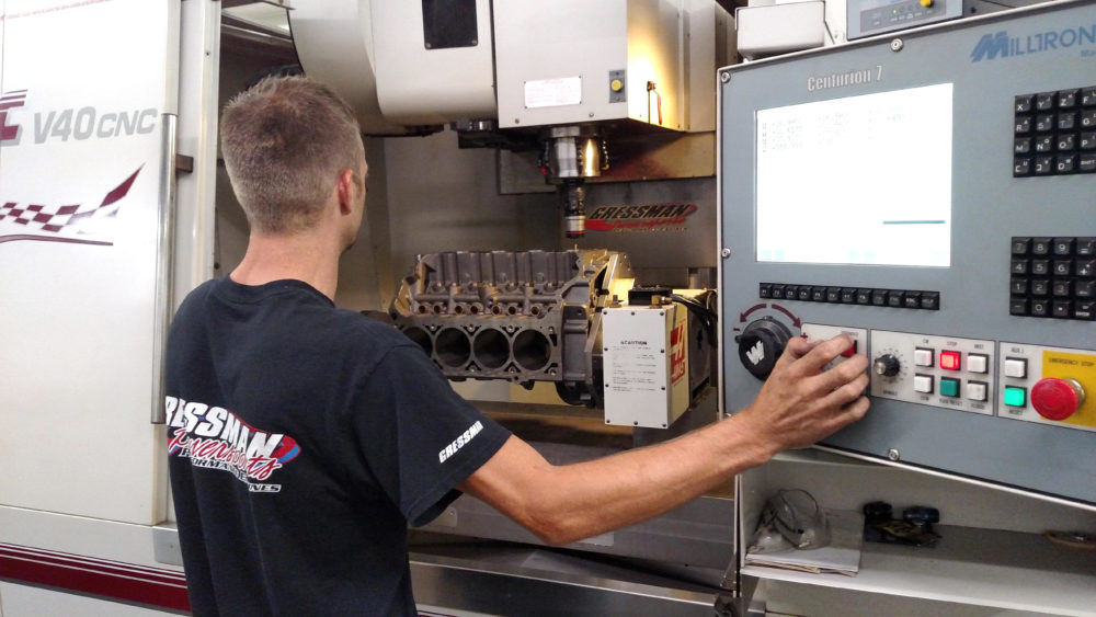
The block was checked and final machined on Gressman Powersports’ CNC machining center. The decks were machined to 9.235″ to make them equal height and parallel to the main bore centerline. After decking, the top edges of the cylinder bores were lightly CNC chamfered.
Our block’s decks and cylinders were machined at Gressman Powersports in Fremont, OH. Out of the box, the cylinder bores measured 4.119 inch. Deck height measurements ranged from 9.236 to 9.240 inch. Scott Gressman CNC-decked the block to a uniform deck height of 9.235 inch. Our finished deck height was a pleasant surprise, since I’ve seen OE blocks that needed much more material removed in order to square the decks.
The aluminum top valley plate completes the deck surface ‘footprint’ and accepts the inboard pinch head bolts. It must be mounted to the block prior to deck surfacing. The plate sat approximately 0.030 inch above initial deck height when installed on the block. Now we could mill the block decks and the plate’s deck surfaces at the same time to get equal deck height and make the valley plate surface parallel to the decks.
This aluminum valley cover base must be used with the Motown II LS block. The angled sides extend the block’s deck surface to complete the mounting surface for the LS cylinder heads. The base must be in place during deck machining to make it fully flush with the block deck surface.
The cylinders needed just a honing to reach the finished diameter. With deck plates installed, the cylinder bores were first honed with 200-grit stones, followed by four strokes with 500-grit stones, and finished with three strokes using plateau brushes. The final 4.1240 bore size provides 0.004 inch of piston-to-wall clearance for our JE pistons.
The lifter bore bushings were machined at Ross Racing Engines in Niles, OH by owner Tony Lombardi. We ordered the block with bronze lifter bore bushings designed for lifters up to 0.904 inch in diameter. Lombardi sized the lifter bores to 0.9047 inch, providing 0.0017 inch of oil clearance for our 0.903 inch hydraulic roller lifters.
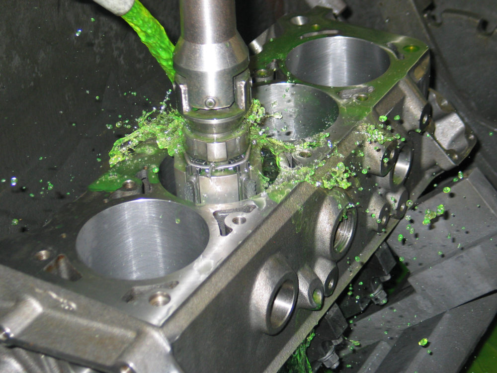
The cylinder bores were final-honed to 4.1240″ to provide 0.004″ piston-to-wall clearance. A few strokes with plateau brushes did the final cleanup, evening out the microscopic peaks and valleys in the wall surfaces.
Painting and Lifter Valley Sealing
Once the block was back from the machine shop, it was thoroughly washed and dried, and the cylinder walls, decks, and main saddles were coated with a light oil. I masked the block and painted it Chevy “Orange-Red” using Dupli-Color engine enamel.
I applied Glyptal high-heat enamel to the lifter valley and the timing chain area at the front of the block to seal the surfaces and improve oil drainback from the valley. Note that the surfaces must be absolutely clean and dry before applying Glyptal.
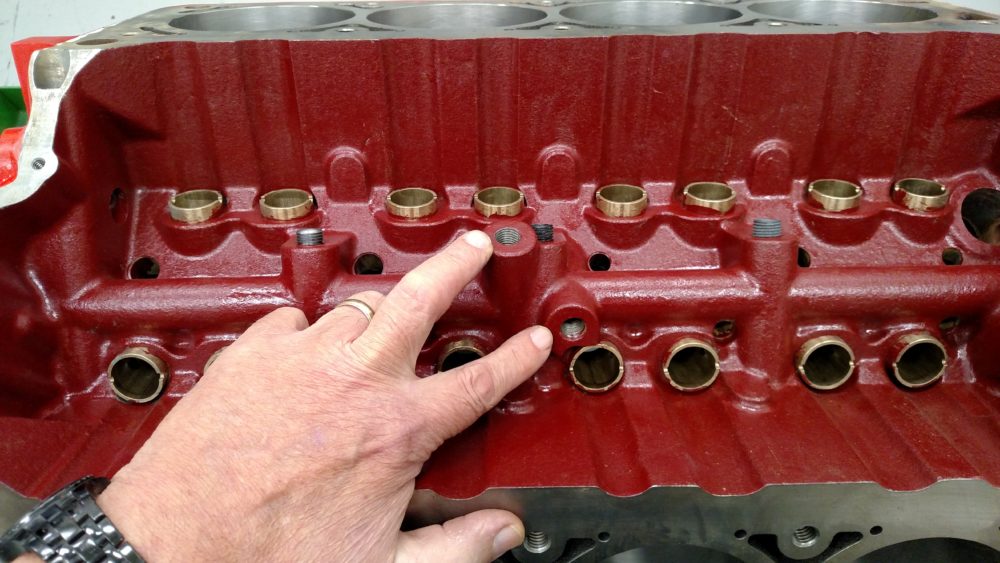
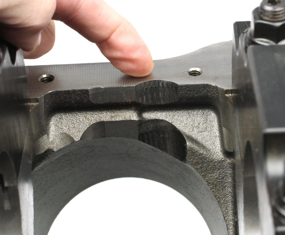
The lifter valley features five holes tapped for 1/4″ NPT plugs. The two pointed out in this photo also feature 1/8″ NPT threads deep inside. If you’re running solid lifters, drilled 1/8″ NPT restrictor plugs must be installed in these two locations to restrict oil to the valvetrain. Since we’re running hydraulic lifters, we only installed 1/4″ NPT plugs.
Installing Cam Bearings
The Motown II LS block features 2.282-inch cam bores. World Products moved the cam oiling passages from the traditional LS position of 6 o’clock to 5 o’clock. With the oil holes at 6 o’clock, the camshaft can be forced down under high spring pressure, severely restricting oil delivery to the cam bearings. Relocating the oiling holes eliminates that concern.
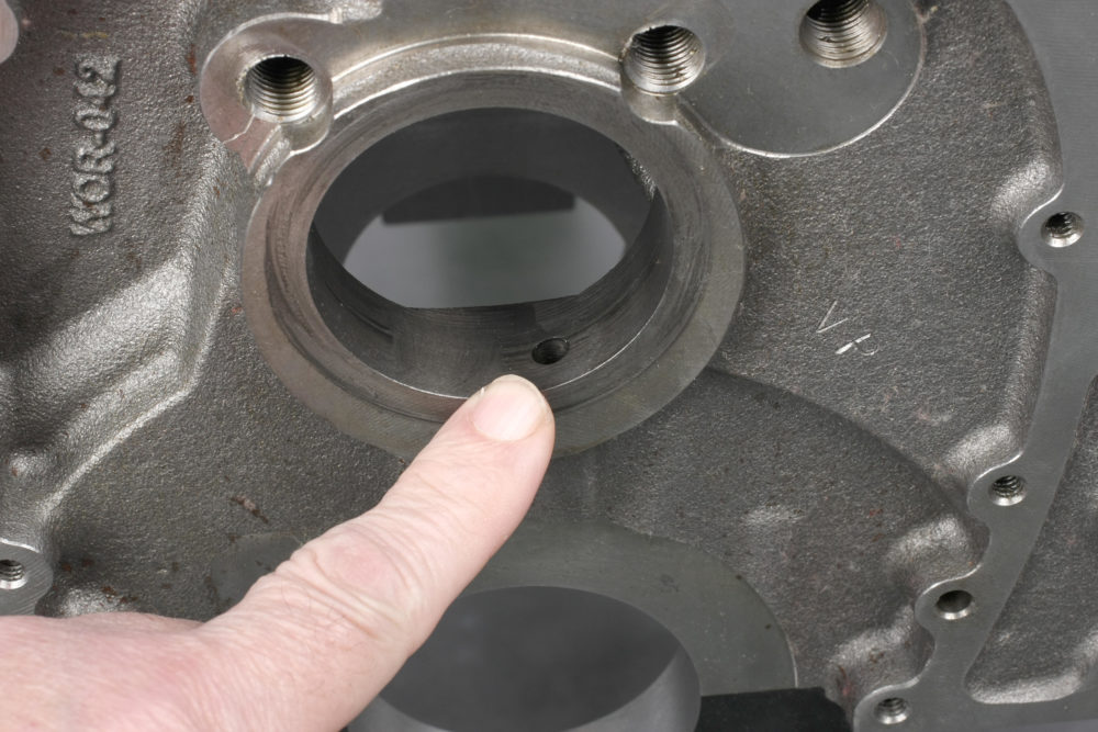
The camshaft location is raised .134″ from the Gen 1 small block location. The cam bearing oil feed holes are relocated to the 5 o’clock position, so pay attention to this when installing cam bearings.
World Products recommends using Dura-Bond GMP55 cam bearings, available uncoated or coated. The bearings have a 2.288 inch O.D. and a 2.174 inch I.D. This provides a theoretical oil clearance of 0.0015 inch with the 55mm cam journals. The Dura-Bond bearings feature a grooved outer diameter, but it’s still necessary to align one of the bearing’s oil holes with the hole in the bore.
As delivered, the Motown II LS block’s cam bores had slight burrs at the bore entrances. I lightly chamfered each bore entrance prior to installing the bearings. When planning a build using this block, be sure to check the cam bore entrances and deburr as needed.
Camshaft
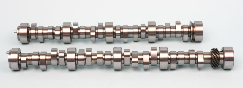
Compare a standard LS cam (top) with the custom Erson hydrualic roller cam for the Motown II LS. The Erson cam features LS lobe spacing, a distributor drive gear at the rear, and a nose that accommodates a Gen 1 small bock timing gear. The cam specs in a .624” of lift (with 1.72:1 rockers) and 243° intake/251° exhaust duration @ 0.050”. LSA (lobe separation angle) is 114°.
As mentioned, cams for the Motown II LS block are currently available only from Erson or COMP Cams on a custom-order basis. Both hydraulic and solid versions are available. The design is essentially an LS cam using a longer core with a rear distributor drive gear. Instead of the stepped cam journal diameters like the LS, all cam journals are 55mm. The nose accepts a small block Chevy cam sprocket. Firing order retains the LS order of 1-8-7-2-6-5-4-3.
I asked Erson to duplicate a hydraulic roller profile I’ve used in previous LS builds. The part number is #54-462-11. The grind number is 293LR HR14 with these specifications:
- RPM Range: 2,600-7,200
- Valve Lift (with 1.72:1 rockers): 0.624″ intake and exhaust
- Duration @ 0.050″ lift: 243° intake/251° exhaust
- Lobe Lift: 0.363″ intake and exhaust
- Lobe Separation: 114°
- Intake Centerline: 111°
When I ordered the cam, I noted that our lifters had a .801-inch roller wheel diameter instead of the standard 0.750-inch wheel found on a stock LS lifter. The increased wheel diameter provides about one degree to 1.5 degrees of additional duration, so Erson compensated for this when the cam was ground.
Crankshaft and Connecting Rods
The block comes notched for rod clearance when using a crankshaft up to 4.000″ stroke. Test fitting with our Scat crank and 6.125″ connecting rods showed no additional block clearancing was needed.
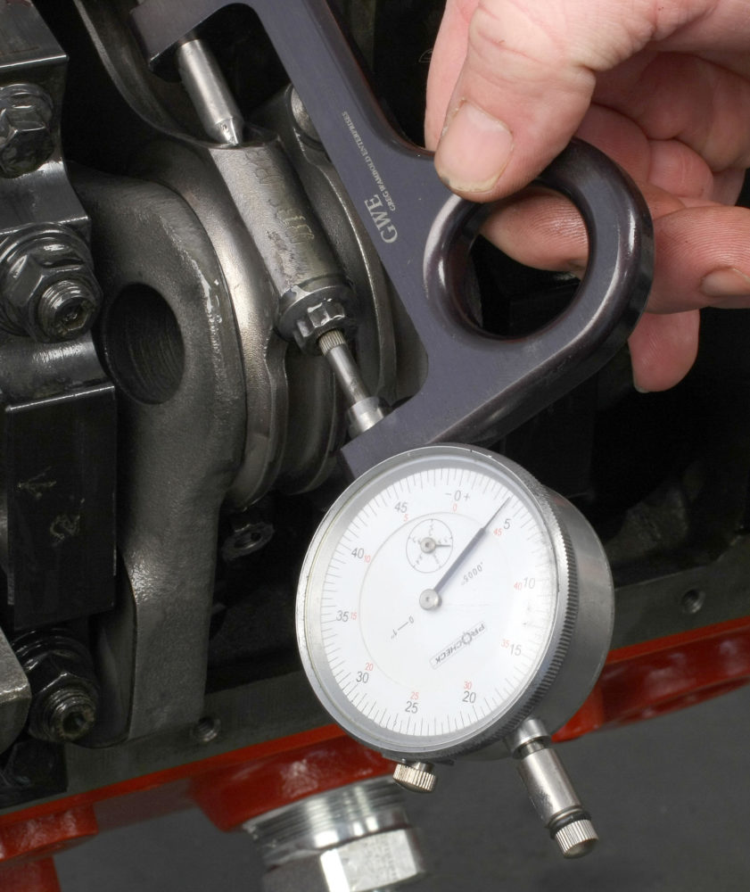
Our four-inch stroke Scat forged steel crank features Gen 1 350 main and 2.100-inch rod journals. The crank was test-fit for counterweight to block clearance, main bearing clearance, and end play before the block was machined. I used Clevite standard main bearings and measured oil clearance of 0.0026 inch by comparing the crank journal O.D. with the installed bearing I.D. Crank end play measured a comfortable 0.006 inch.
We also test-fit the Scat H-beam connecting rods to determine rod big end and rod bolt clearance to the block. We found more-than-adequate clearance at all points, with the tightest clearance being 0.180 inch. No additional block machining was required.
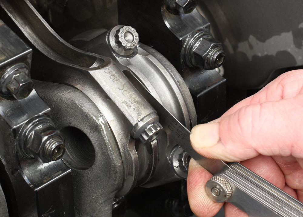
Rod side play checked out at 0.017-0.018″. Crankshaft end play measured 0.006″.
During our bearing clearance check, I measured the rod pins at 2.100 inch. A dial bore gauge was zeroed at this dimension and rod bearing oil clearance was checked using a set of standard rod bearings. I got 0.002 inch of clearance with the rod cap bolts torqued to 64 ft.-lbs. To get a bit more oil “cushion” for the rod bearings at high rpm, I used Clevite CB663HN standard upper and CB664HXN 1x lower bearings to get 0.0025 inch of oil clearance.
The rotating assembly was balanced at Creston, OH-based Medina Mountain Motors. After the initial crank spin on the balancer, we found weight had to be removed from the front and rear counterweights to accommodate the lightweight JE pistons. Medina Mountain Motors owner Jody Holtrey removed a total of 207 grams from the crank counterweights. Final balance was achieved at -0.9 grams front and -1.2 grams rear, well within the acceptable range. As a point of reference, a single U.S. dollar bill weighs a mere 1 gram.
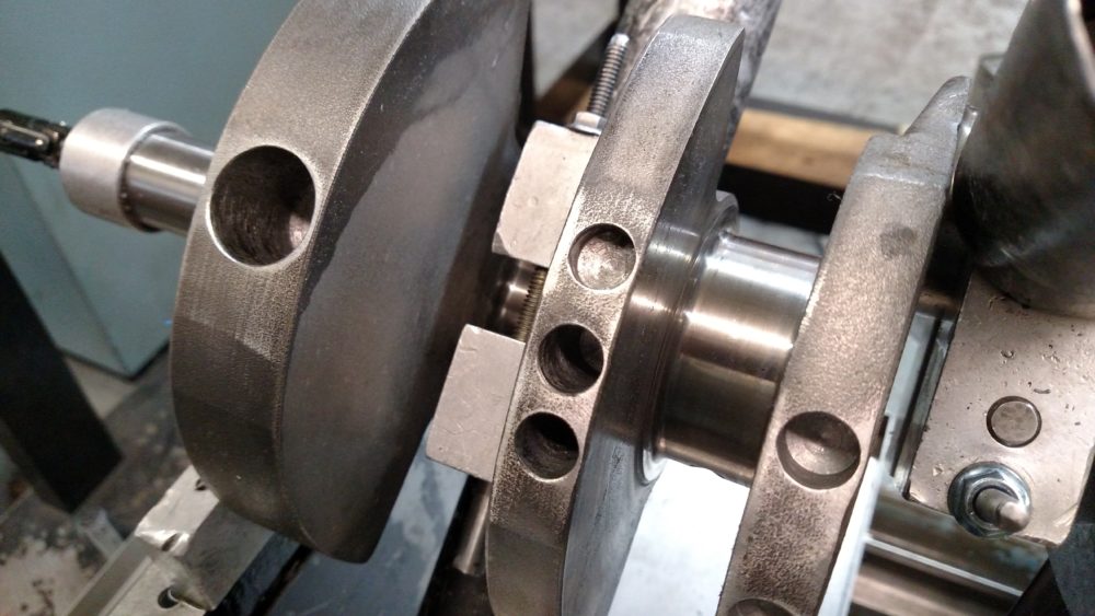
Our Scat forged steel crank features a 4.000″ stroke and 2.100″ rod journals. Weight reduction was required for balancing. Medina Mountain Motors’ owner Jody Holtrey removed a total of 207 grams from the crank counterweights. The crank was final balanced at -0.9 grams front and -1.2 grams rear.
Bottom End Assembly
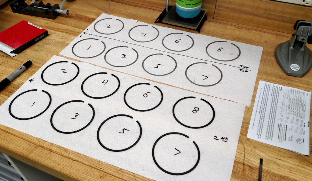
Top and secondary piston rings were individually file-fit for specific cylinders to insure consistent end gaps.
We used Total Seal piston rings. For a high performance application, JE recommends gapping the top rings at bore diameter x 0.0045 inch and the secondary rings at bore diameter x 0.005 inch. I file-fit the top rings to a gap of 0.019 inch and secondary rings to 0.020 inch using my bench-mounted Summit Racing ring filer. The rings were squared in the bores using a Summit Racing adjustable ring squaring tool. I fit all rings on a per-cylinder basis, organizing ring sets for each specific cylinder.
The connecting rods were fitted to the pistons with the supplied floating pins and secured with wire clips. Pins were lubed with Royal Purple Max Tuff assembly lube. Oil ring support rails were necessary because the pin bore intersects the oil ring groove. The raised dot on the support rails must face down over the center area of the pin bore. This prevents the support rail from rotating out of position and keeps the end gap from entering the pin bore area.
Our ARP rod bolts, coated with ARP Ultra lube, were torqued to 64 ft.-lbs. and checked for stretch, which averaged 0.0040″.
The block cylinder walls were thoroughly cleaned with white lint-free towels and lacquer thinner, then coated with 30W non-detergent oil. I used a Summit Racing adjustable ring compressor to compress the piston rings as I slid the piston/rod assemblies into the bores. A long-nose piston hammer gave me enough reach to nudge the pistons down as I guided the rods onto the crank’s rod journals.
Stretch was checked on the ARP rod bolts. Scat notes that rod bolt stretch should not exceed 0.0046 inch at 64 ft.-lbs. of torque. Each bolt’s stretch measured a tight average of 0.0040 inch.
Connecting rod side play measured a consistent 0.0017-0.0018 inch at all rod journals.
Timing Set Installation and Camshaft Endplay
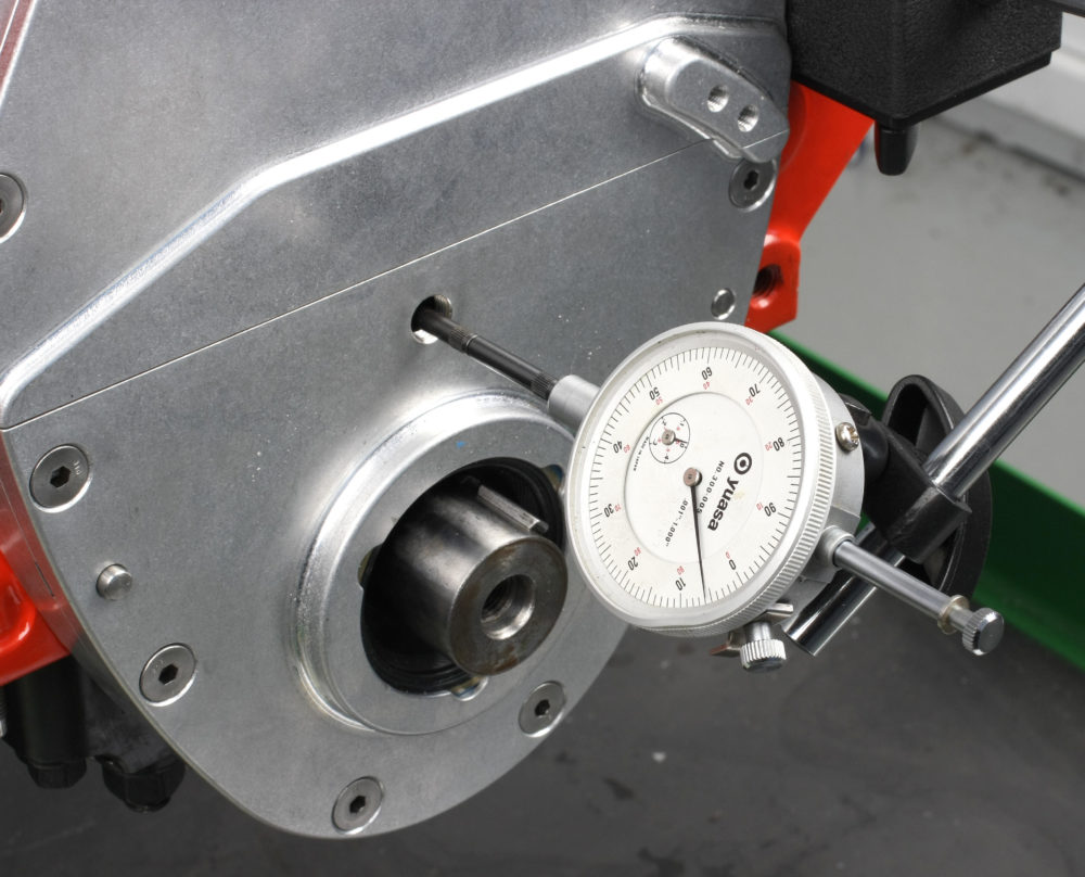
I installed a COMP Cams roller thrust bearing to limit and adjust camshaft end play. Shims are placed between the cam and the bearing to adjust final end play. A dial indicator was used to monitor cam end play as the cam is pushed back and forth.
Since the cam bore centerline is raised 0.134 inch in the block, a special timing set is required. Stock Gen I Chevy cam-to-crank center distance is 4.521 inch, but the Motown LS block’s center distance is 4.655 inch. Cloyes supplied a prototype set for our build, and it should be available as of this writing.
The roller thrust bearing was secured to the cam sprocket with the three-bolt retainer plate included with COMP Cams timing cover set. I normally use ARP cam bolts, but clearance issues with the thrust bearing meant I had to use the 5/16 inch-18 Torx head cap screws that come in COMP Cam’s timing cover kit.
After installing the thrust bearing in the cam sprocket, cam end play measured 0.055-0.056 inch—more than the .005-.010 inch ranged COMP recommends. I added three 0.010 and one 0.020 inch shims between the cam nose and thrust bearing to reduce endplay to 0.006 inch. This is critical to prevent the roller cam from walking, keep the cam lobe edges from contacting the lifters, and to keep the lifters centered on the cam lobes. After adjusting cam endplay, the cam and crank sprocket faces were checked for fore/aft play. It measured 0.002 inch.
During cam gear and chain test fitting, the two outer ¼-inch NPT plugs on front of the block were a bit too close to the rear of the cam gear. I removed the plugs and shortened them by about 0.045 inch on my lathe, which gave me the clearance I wanted.
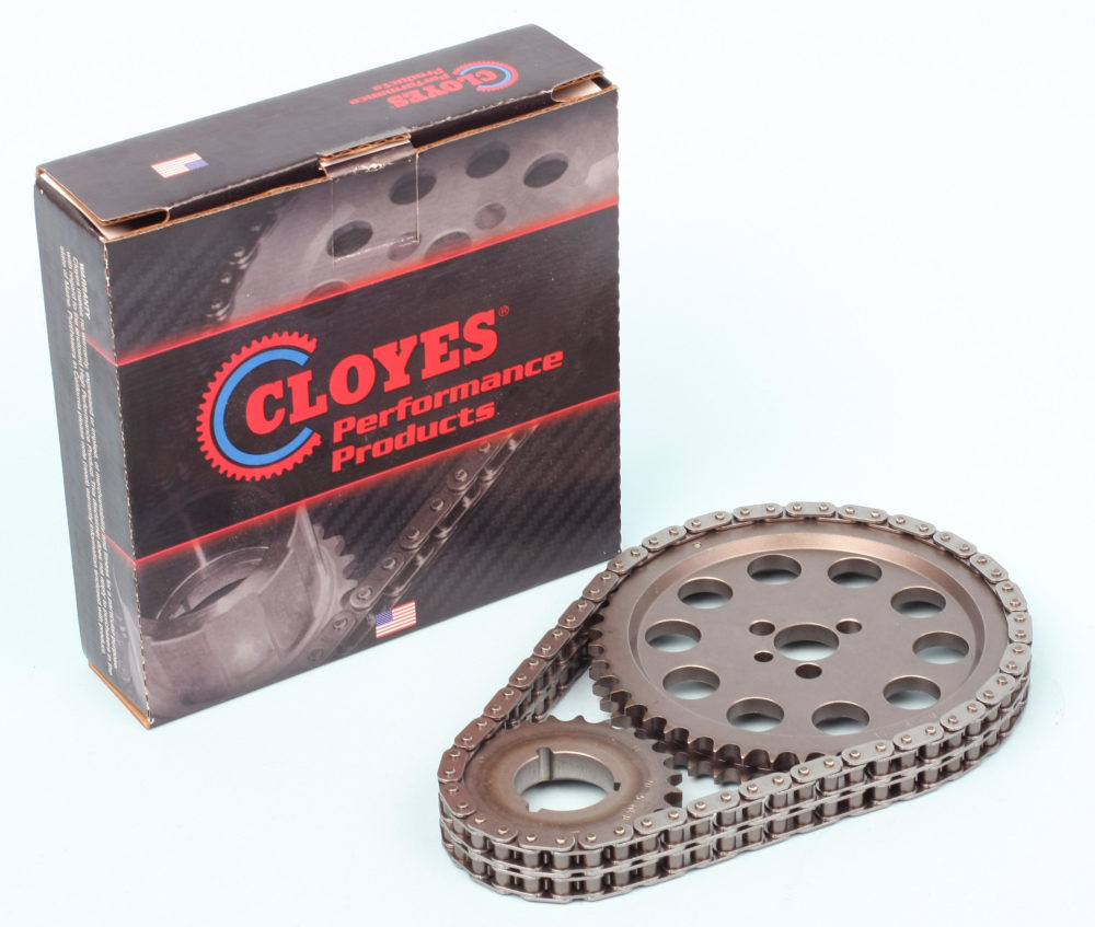
Cloyes provided a special timing set to accommodate the block’s 0.134″ raised cam bore. The set features a 3-way adjustable crank gear.
The two-piece COMP timing cover kit has an aluminum spacer ring that installs on the block; the lower and upper covers attach to the ring. The lower cover plate features a 1/8-inch NPT inspection hole to accommodate a dial indicator when checking cam end play. The upper cover has a plate that can be removed to swap cams without disturbing the oil pan. The timing cover kit includes black oxide fasteners, but I opted to use stainless steel screws.
Oil Pump
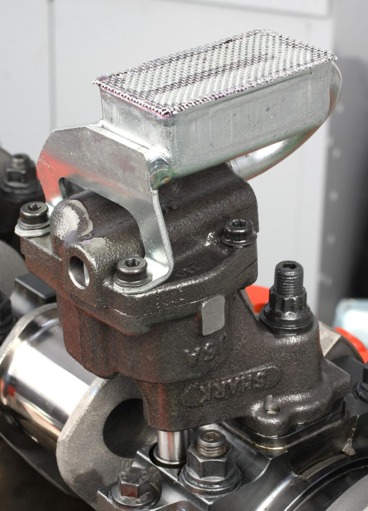
This is the Melling high volume Gen 1 style oil pump fitted with the Moroso pickup designed for our Moroso pan. The pickup features a bracket that bolts to the oil pump cover, so there is no need to weld or braze the interference-fit tube to the pump.
I ordered the block with billet steel main caps. The rear main cap has the mounting base for the oil pump, but no dowel pins were supplied to register the pump to the cap. I installed a pair of 0.250 x .625 inch steel pins which provided an excellent interference fit to the main cap.
Prior to installing the Melling high volume oil pump, I removed the cover and applied lube to the gears. I installed the Moroso pickup recommended for our Moroso oil pan and snapped the Melling intermediate shaft onto the pump drive, then bolted the oil pump assembly on the rear main cap using an ARP stud kit. The stud nut should be torqued to 55 ft.-lbs. Due to the location of the Moroso pickup, access to the stud nut required the use of an offset torque wrench extension. To compensate for the added leverage length with the extension, I set my digital torque wrench to 48.12 ft.-lbs.
Short Block Measurements
- Block Deck Height: 9.235″
- Cylinder Bore Diameter: 4.1240″
- Lifter Bore Bushing ID: 0.9047″
- Lifter Bore Oil Clearance: 0.0017″
- Crankshaft Main Journals: 2.4483″
- Main Bearing Oil Clearance: 0.0026″
- Crankshaft Rod Journals: 2.100″
- Crankshaft End Play: 0.006″
- Connecting Rod Pin Width: 1.900″
- Connecting Rod Bearing Oil Clearance: 0.0025″
- Connecting Rod Sideplay Clearance: 0.017-0.018″
- Connecting Rod Bolt Stretch: 0.0040″
- Piston to Wall Clearance: 0.004″
- Top Piston Ring Gap: 0.019″
- Secondary Piston Ring Gap: 0.020″
Is there a total cost in this endeavor? Really curious if it might be somewhat “kinda close” to building a strong SBC/ with AFR heads that would make comparable torque and power?
[…] [Read the first half of this story here: Best of Both Worlds: Building a Gen 1/LS Hybrid with World Products’ Motown II LS Block (Part 1).] […]
It will cost way more than a sbc with afr heads.
I think that going with this package is really neat but very costly. If you are going to go “class racing” it might be of great benefit, but for a street guy like me, I would spend the $10,000 on a BBC and save the extra $3500.00 left on wheels and tires or a trans upgrade.
You could also get close to the 641h.p.with a 427″ (4.065×4.100″) LS long block from Scoggins Dickey Chevy; there was a lot of secrecy with the pistons so we don’t know the finished compression or amount of work that went in to the heads either.
Still, very pretty and only in my dreams.
Can I simply say what a relief to discover someone that truly
knows what they’re discussing on the internet.
You definitely understand how to bring a problem to light and make it important.
A lot more people need to check this out and understand this side of your story.
I can’t believe you are not more popular given that you
definitely have the gift.
Butch Shaw (DRSE RACING); This info is very important for me because I’m a diehard sbc fan from the 60’s with a 79 Z/28 and I was considering putting a LS Hybrid in it because its a neat setup but I haven’t really checked details until now. I’m gonna go with my original plan; a 434ci GEN 1 with AFR heads mainly because its simpler and cost efficient and a step up from the 327 I’ve been running in it since I graduated high school in 77′. Before that I had a 283..
Thanks again for the info…
If I have 23 degree pistons, which or what Cylinder heads are required, will I be able to use 13 degree heads.
I like every thing about it, I have been beating my head over this in what to do for my 83 Chevy s10, Ford 9in 18.5 tires full cage, 671 blower 2x 750 Holly e85, to build this power you don’t have a street able car, ls heads change this, no spread blow off set solid lifters, I’m worried if I can get all the parts to do this all