Editor’s Note: Mike Mavrigian must do nothing but build engines and write stories about them. We have visions of his shop, Birchwood Automotive, set deep in the woods with Mavrigian keeping little forest creatures for friends.
His latest engine build is a 427—well, it’s a hybrid of sorts that blends the best of the Gen 1 small block Chevy and the GM LS series engines. It’s a combination made possible by World Products’ Motown II LS block, which allows the use of free-flowing LS cylinder heads on small block Chevy architecture. In this case, the combination produced a respectable 641 horsepower at 6,300 rpm, and 555.7 foot-pounds of torque at 5,200 rpm. Now, in the second of this two-part article about this engine build, Mavrigian walks us to the finished product.
[Read the first half of this story here: Best of Both Worlds: Building a Gen 1/LS Hybrid with World Products’ Motown II LS Block (Part 1).]
…
Cylinder Heads
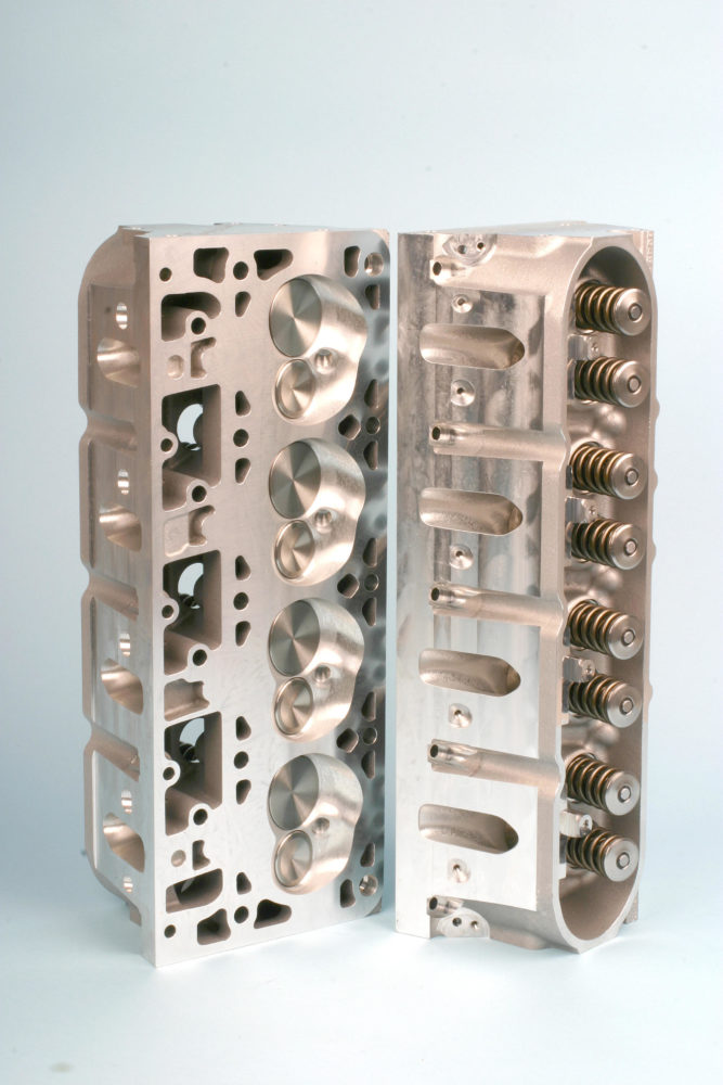
I opted for a pair of Trick Flow GenX® 235 cathedral port cylinder heads with 235cc intake runners, 80cc exhaust runners, and 70cc heart-shaped combustion chambers. These heads are fully CNC-finished with a premium high-resolution finish for maximum flow. I checked combustion chamber volumes and they all measured exactly as published. Other features include:
- Intake and exhaust valve angles moved to 13.50 degrees to decrease valve shrouding
- Spark plugs relocated to enhance mid-lift airflow and increase casting rigidity
- Material added at the rocker arm mounting bases to increase high-rpm valvetrain stability
- 2.080-inch intake/1.600 exhaust valves
- 1.300-inch dual valve springs
- 7-degree valve locks and titanium retainers
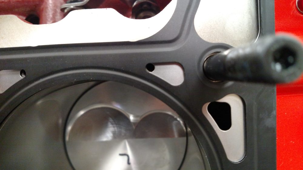
The GenX 235 heads were installed with ARP 7/16-inch studs torqued to 75 ft-lbs. using ARP assembly lube. The Fel-Pro MLS head gaskets have a compressed thickness of 0.041 inch and 4.165-inch gasket bore diameters.
Rocker Arms
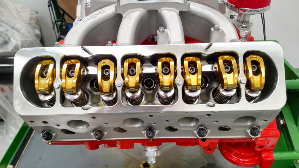
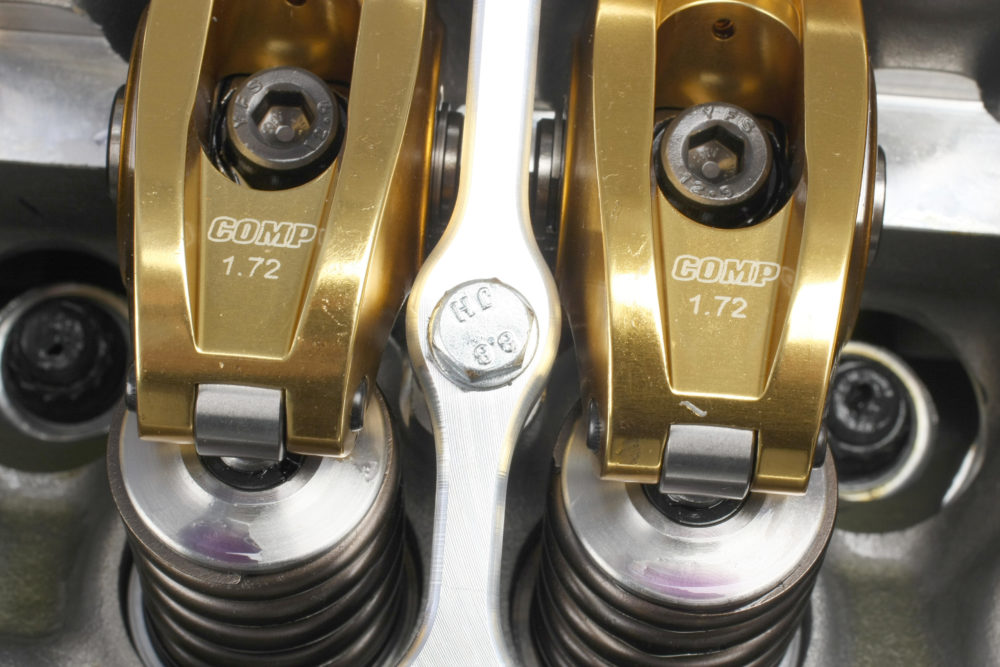
I chose COMP Cams Ultra-Gold ARC Series roller rocker arms. The bodies are CNC-extruded aluminum for added strength to handle high valve spring loads. Larger-than-stock billet steel trunnions have captured needle bearings. The kit includes mounting pedestals with radius pockets for the trunnions. The non-adjustable rockers install with socket head cap screws torqued to 22 ft.-lbs.
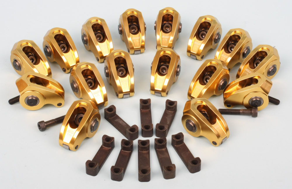
The Ultra-Gold rocker arms are pretty beefy but have a profile that clears aftermarket valve covers. Clearance could be an issue with OEM valve covers unless you use valve cover spacers. I used tall style Gen 1 small block covers with COMP’s billet adapters. The rockers clear by a mile.
Pushrods
Since we’re using non-adjustable rockers, pushrod length is critical. Careful measuring showed we needed 7.500-inch long pushrods. I ordered a set of 5/16-inch, 0.80-inch wall pushrods.
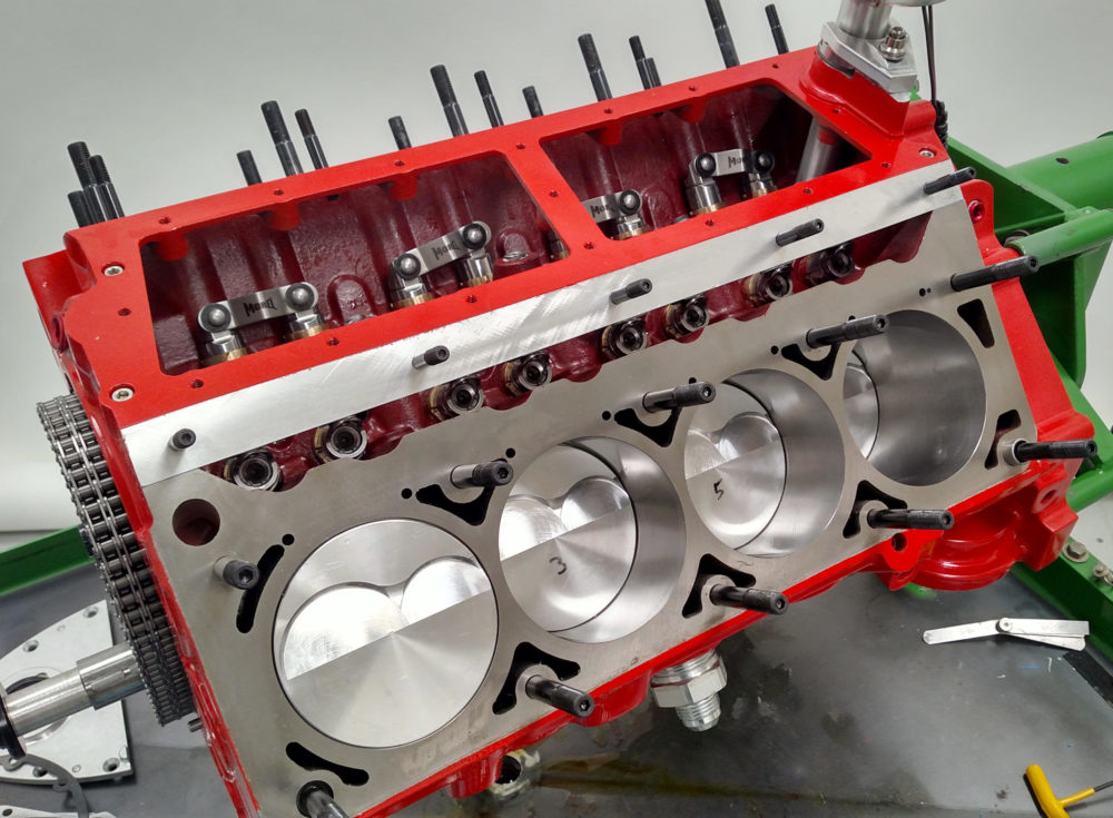
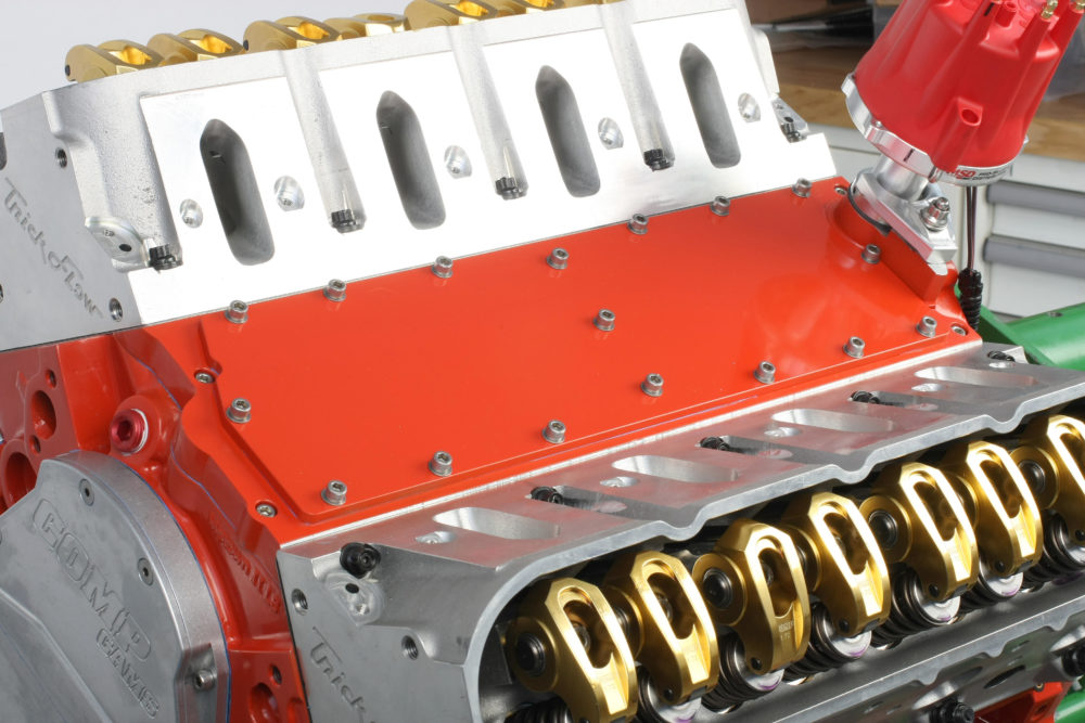
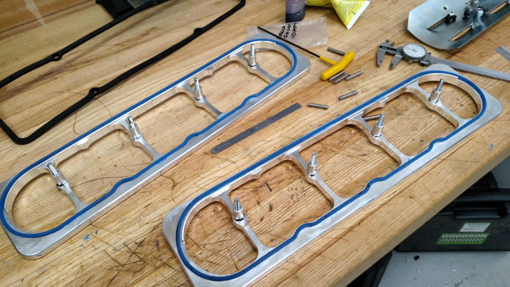
Valley Cover Assembly
The two-piece World Products aluminum valley cover has a base that secures to the block and a cover plate. After installing the lifters, I applied a thin bead of Permatex Ultra Blue RTV to the block rails and secured the base to the block with four stainless 1/4-20 x 7/8-inch socket head cap screws—two at each rail.
I temporarily installed both cylinder heads without gaskets to properly align the angled sides of the valley base with the heads. That provides a flush continuation of the block decks. I torqued the base screws to 80 in.-lbs. and removed the heads.
I had a slight alignment issue on the right side of the valley cover base. The row of 5/16-inch-18 screw holes sat a tad too high to allow proper alignment between the bolt holes in the head and the openings in the head gasket at the inboard pinch bolt locations. I slightly enlarged the pinch bolt holes on the passenger side cylinder head to 7/16-inch, and opened the holes in the head gasket to 0.400-inch. I also had to slightly grind the inboard side of the pinch bolt hole bosses so the washers would sit flat.
The valley cover plate goes on after the heads and pushrods are installed. It secures to the base using a thin bead of RTV and 17 stainless 1/4-20 x ½-inch socket head cap screws and 0.468-inch OD flat washers. All screws were snugged to 80 in.-lbs. with medium-strength Loctite applied to the screw threads.
NOTE: Make sure all 10 5/16 inch-18 threaded holes on the angled sides of the valley cover base are chamfered and clean. The milling cut leaves sharp edges at the holes that will likely prevent bolt or stud installation.
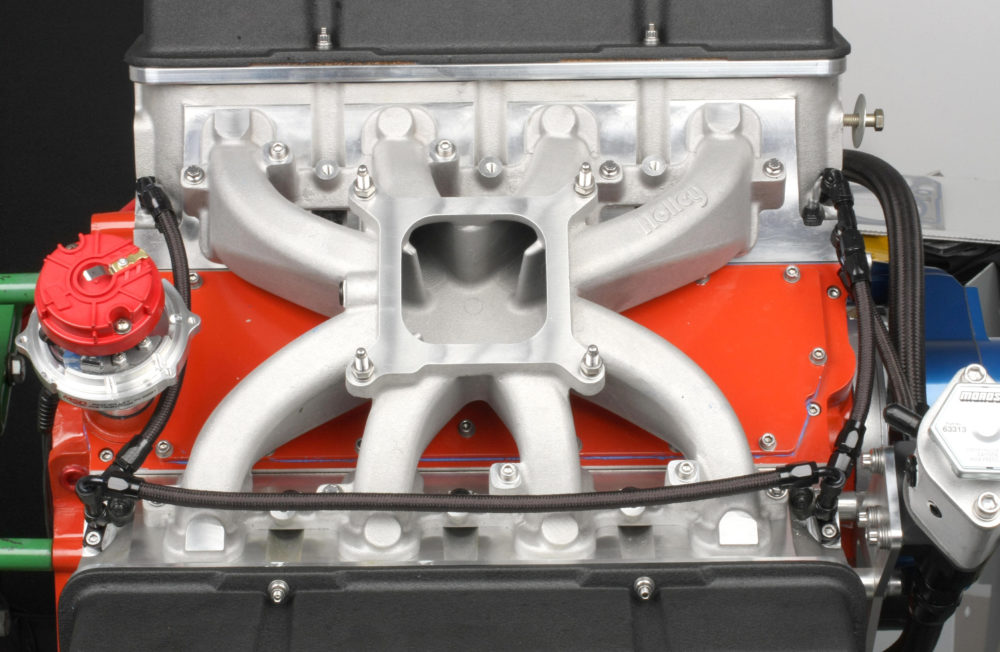
Intake Manifold
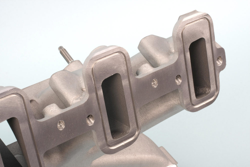
I opted for a carburetor setup instead of fuel injection. I chose a Holley ‘mid-riser’ single plane intake manifold. The intake and cylinder head port match is nearly dead-on, with only a minimal amount of work needed in a few spots. I did not make any modifications to the plenum so I could establish a baseline during the dyno session. A bit of smoothing and radiusing of the plenum dividers would likely provide a slight power increase.
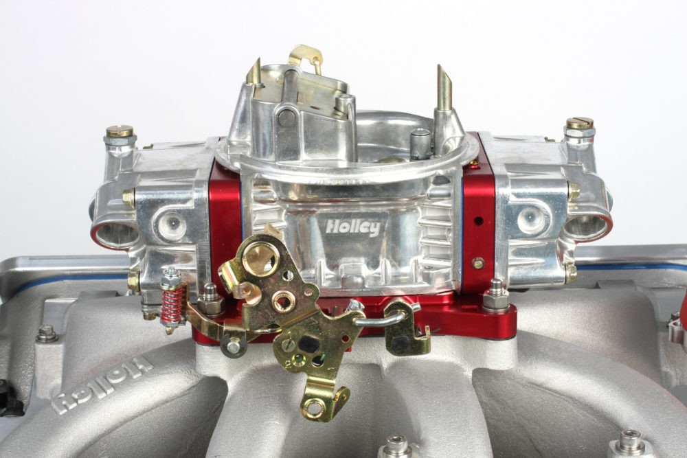
The manifold hardware kit has bolts for both LS1 and LS3 applications. Our engine needed the 80mm LS1 bolts; I opted to use ARP polished stainless screws. After installing the supplied O-rings in the grooves around each manifold intake port, I bolted the manifold to the engine. Holley’s instructions recommend applying engine oil to the bolt threads. I used ARP Ultra Torque assembly lube, which reduces friction better than oil.
Valve Covers
I used Summit Racing aluminum valve covers with COMP Cams valve cover adapters. Other valve cover adapters I’ve tried required time-consuming modification in order to clear aluminum roller rocker arms. The COMP adapters were a refreshing change, requiring no clearancing at all.
The adapters have stand-off spacers, and it’s difficult to place all four spacers and adapters into position at the same time. I lightly glued the standoff spacers to the underside of the adapters to keep the spacers in place during installation.
The adapters’ head-mating surfaces have machined grooves to accept standard LS valve cover gasket seals. However, the grooves were machined a bit on the wide side and wouldn’t hold the seals in place. I put very small dabs of RTV in the grooves before installing the seals to keep them from falling out during installation.
Timing Cover
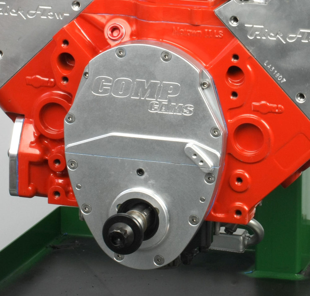
The COMP Cams three-piece timing cover has a base that seals to the block with a small block Chevy timing cover gasket. RTV must be used to seal the lower and upper cover plates since there is no provision for gaskets or O-rings. The 1/8-inch NPT inspection plug was installed in the lower cover with thread sealant. All timing cover bolts were torqued to 80 in.-lbs.
Oil Pan
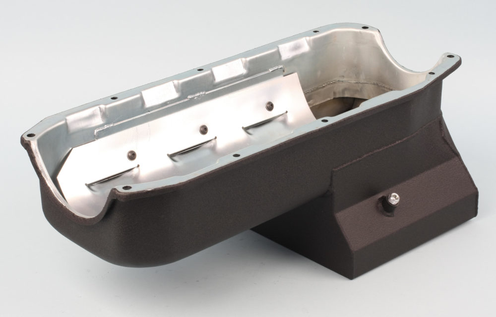
Our 7-qt. Moroso Street/Strip oil pan has a built-in baffle, a windage tray, and an 8.250-inch deep rear sump. I had it powdercoated in wrinkle black to match the valve covers. Using a one-piece silicone pan gasket sounds good in theory, but I found that style to be far too thick to obtain a proper seal, especially at the front seal area. That’s why I opted for the four-piece Fel-Pro gasket set that World Products intended for this block. The gasket set includes both a “thin” and “thick” front seal where the pan front radius meets the bottom of the timing cover. We had to use the thicker front seal.
Water Pump
The upper left (driver side) bolt is open to water, so thread sealant is required.
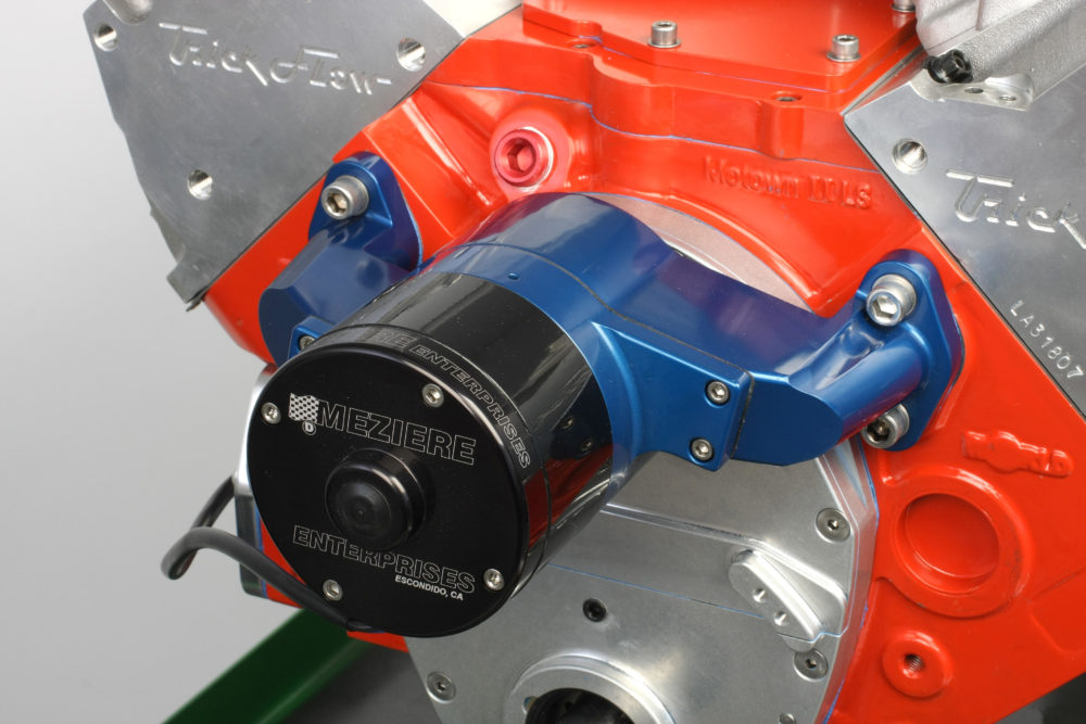
Meziere electric water pumps are always my first choice. They function flawlessly and eliminate the need for a drive belt, reducing parasitic power loss. The pump offers a free-flow rating of 55 gpm, which is more than adequate. The aluminum bodied pump weighs a mere 7 lbs. and features a stainless steel main shaft and ceramic seal. There is plenty of room between the pump and the COMP timing cove, so there’s no need to modify anything for clearance.
The pump came with 1.250-inch long bolts that were too long for the tapped holes in this particular block, so I used 1.125-inch long bolts. The driver side pump bolt hole in the block is open to water and must be sealed with thread sealer. All bolts were torqued to 10 ft.-lbs. with a final torque of 25 ft.-lbs.
Harmonic Damper
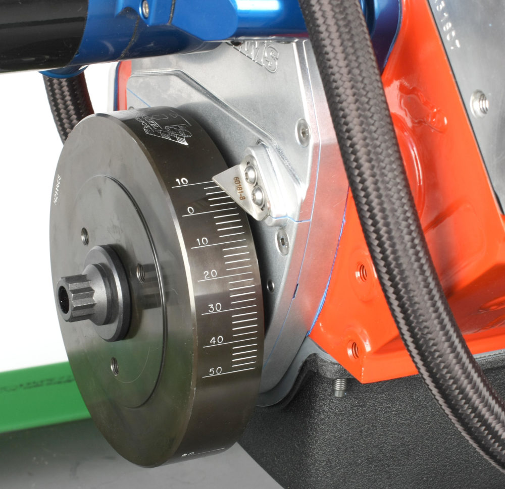
Our Fluidampr harmonic damper measures 7.250 inches in diameter with a 1.2460-inch bore diameter. The damper is a 0.0015-inch press fit on the 1.2475-inch diameter crank snout. After heating the damper in a convection oven to 220° F, a coating of high-temperature anti-seize was applied to the damper bore and crank snout. The damper was smoothly drawn to seat against the crank gear using a bearing-assisted threaded-mandrel installation tool. The ARP crank bolt was torqued to 80 ft.-lbs. A timing pointer supplied with the COMP Cams timing cover kit was adjusted to indicate zero on the damper.
Water Temperature Sensor
LS cylinder heads have a 12mm x 1.5 threaded hole for a water temperature sensor. Since we’re not running an engine controller, I installed an ICT Billet adapter in the driver side cylinder head’s sensor hole to allow the use of a small block Chevy temperature sender. The passenger side head’s water port was sealed with a 12mm x 1.5 x 20mm bolt and a crush washer. Be sure to apply a bit of lube to the adapter’s male threads; installing it dry in the aluminum head can easily cause thread galling.
Coolant Plumbing
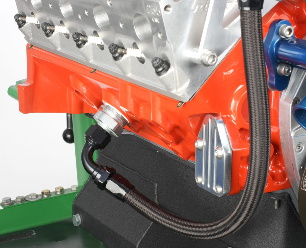
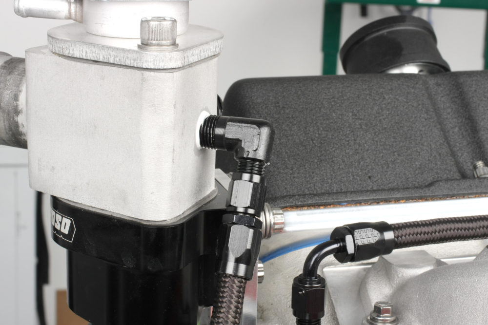
The early version of the World Products Motown II LS block routed external coolant plumbing to the front of both heads. The current version we have features 1 ¼-inch NPT female threaded ports on each side of the block so you can run -12 AN plumbing to a thermostat housing and water neck. They mount to the front of either head using a Moroso adapter bracket.
I mounted the Moroso thermostat housing and water neck to the passenger side cylinder head. The rear of the water neck has one ½-inch NPT and two ¼-inch ports. They can be used for a temperature sender or other sensors or sealed with threaded plugs. A 14-16 lb. Moroso radiator cap seals the water neck.
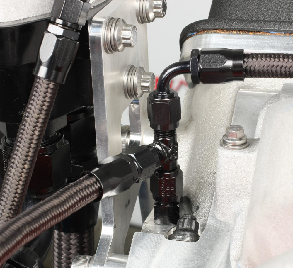
I used Fragola and Aeroquip fittings to plumb the two female -12 AN ports at the base of the thermostat housing to the ports on the sides of the block:
- Two -12 AN straight to -12 AN male fittings in the thermostat housing
- One -12 AN straight hose end (right side port) and one -12 AN 90° hose end (left side port)
- Two 1 ¼ inch to -12 AN male fittings and two -12 AN 90° hose ends
- -12 black braided hose (21-inch length for right side, 23-inch length for left side)
The 90° hose ends at the block ports must be angled slightly inboard toward the oil pan so the hose will clear the motor mount locations.
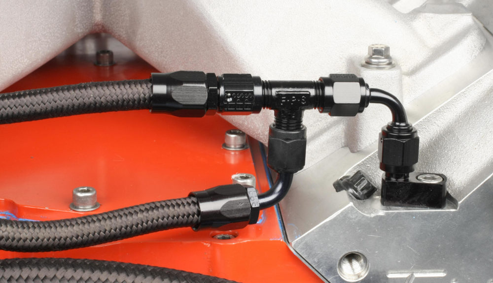
Cylinder Head Steam Plumbing
To properly evacuate air from the cylinder heads and avoid overheating at the rear cylinders, I installed a coolant transfer plumbing system that ties the front and rear cylinder head steam holes together. This system allows air to bleed off into the Moroso water neck.
I used four Trick Flow steam plug fittings and Fragola -4 AN fittings and hose:
Right Front Head
- One female/male/male T-fitting
- One 90° hose end on vertical male of the T-fitting
- Straight hose end on horizontal male of the T-fitting
Right Rear Head
- One male/male/female T-fitting
- 90° hose end on vertical male of the T-fitting
- Straight hose end on horizontal male of the T-fitting
Left Front Head
- One 90° female/female coupler
- One male/male/male T-fitting
Left Rear Head
- One 90° hose end
At Water Neck
- One 90° -4 AN to ¼-inch NPT fitting threads into the rear of the water neck housing. A straight hose end attaches to the -4 AN end of the fitting
Steam Fitting Hose Connections
- Right front to right rear hose: 16 ½ inches long
- Rear right to left rear hose: 8 inches long
- Front left to right rear hose: 4 ½ inches long
- Left front to water neck hose: 7 ¼ inches long
Distributor
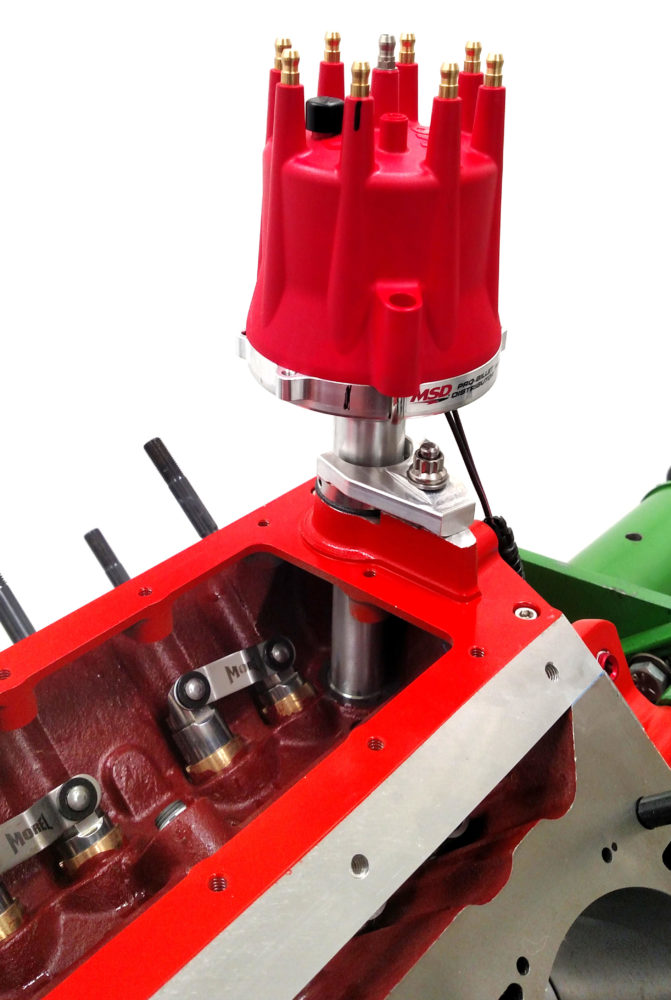
Our MSD Pro-Billet distributor comes with an adjustable-height slip collar and an iron cam gear. Because we’re running a steel roller cam, I swapped out the iron gear for an MSD bronze gear.
I test-fit the distributor to verify that the overlap engagement of the distributor’s driven tang to the Melling oil pump’s drive shaft was approximately 1/4 inch. I also made sure the distributor housing’s oil groove aligned with the oil passage at the upper right rear of the block. This involved installing the distributor until it bottomed out, and then raising the distributor about 0.025-inch. The slip collar was tightened to lock the height setting.
Trick Flow recommends using NGK 4577 spark plugs (gapped at 0.050-inch) with its GenX cylinder heads. I used a universal set of MSD 8.5mm plug wires and routed them along the bottom of the heads and up behind the block to the distributor. The wires’ 90° plug boots tuck the wires closer to the engine.
NOTE: Although the Motown II LS block is based on Gen 1 small block architecture, the camshaft follows the LS format firing order of 1-8-7-2-6-5-4-3, not the small block firing order of 1-8-4-3-6-5-7-2. Make sure to route the spark plug wires accordingly.
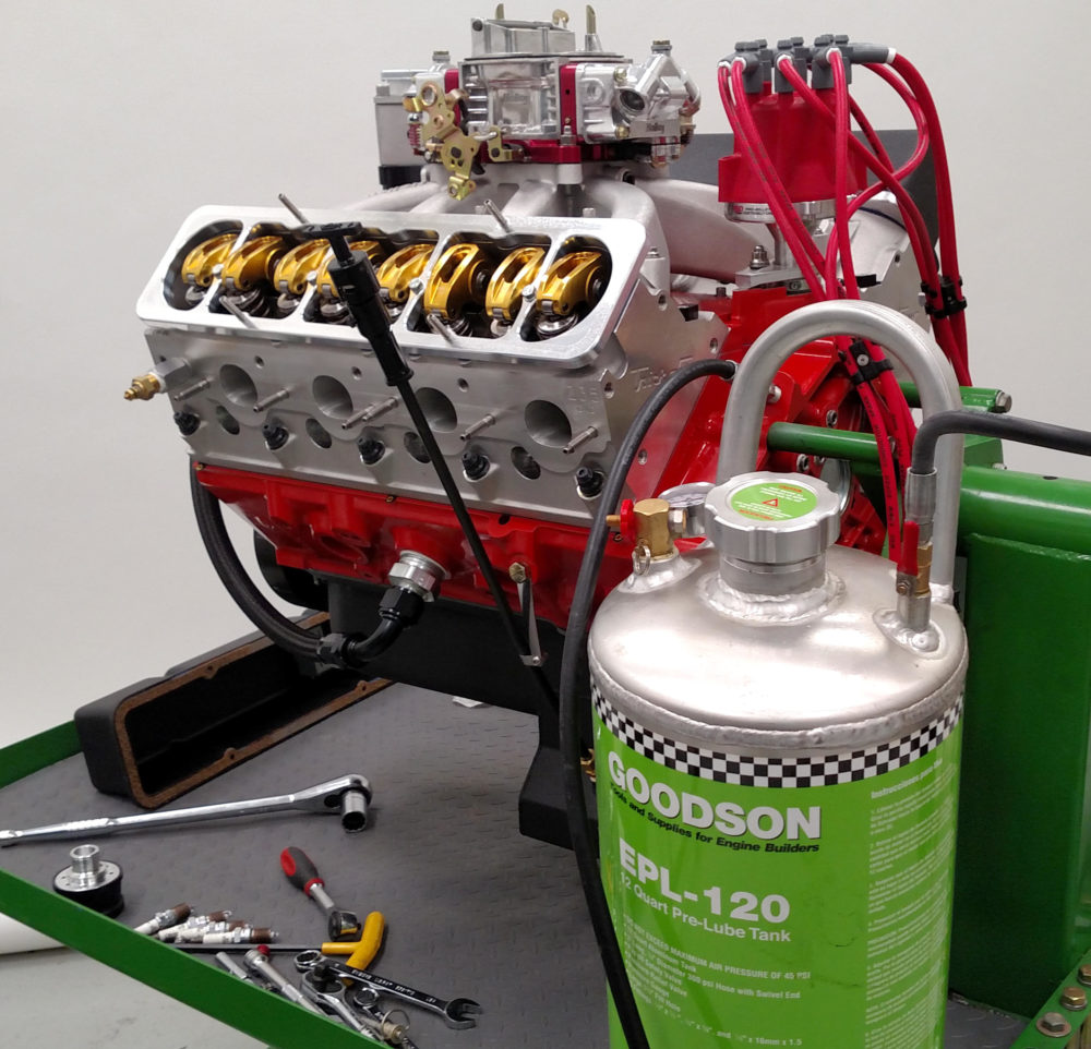
Engine Pre-Oiling
I pre-oiled the engine prior to the dyno test. I filled the pressure tank with oil and pressurized it with 80 psi of compressed air. The tank hose was connected to the block’s ¼-inch NPT sender port. Opening the pressure tank’s valve forces oil throughout the oil passages; I slowly rotated the crankshaft twice (360 degrees) to ensure oil delivery to all bearing-hole feed locations. I then used a drill to turn the Melling oil pump. I drained the oil pan, then refilled it with six quarts and 20 ounces of 5W-30 Pennzoil mineral oil plus 12 ounces of COMP ZDDP break-in lube, for a total of seven quarts.
Dyno Results
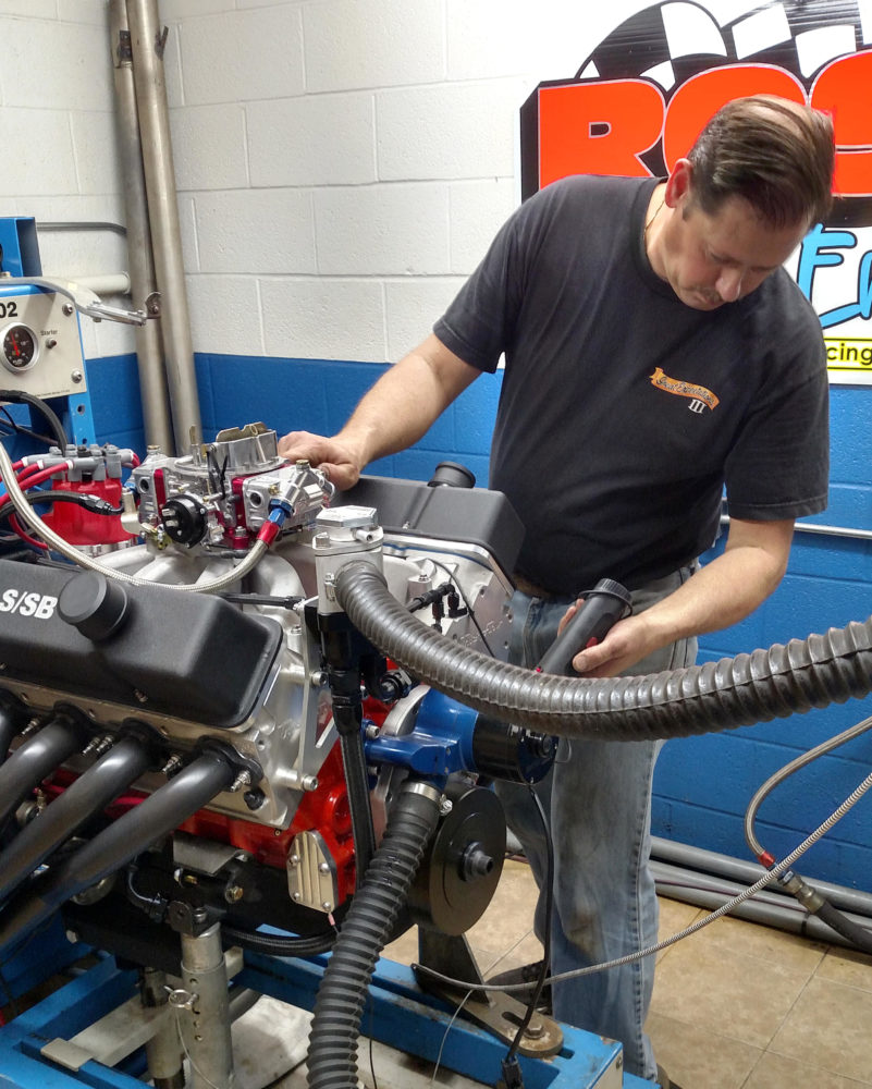
The engine was dynoed at Ross Racing Engines in Niles, OH. Though our time on the dyno was short, we did get the engine to make 641 hp at 6,300 rpm; and 555.7 ft.-lbs. of torque at 5,200 rpm. Swapping our Trick Flow GenX cathedral-port heads for the company’s GenX LS3 style heads, and using either a taller intake manifold or adding a one-inch-tall spacer to the Holley mid-rise intake, would likely add another 20 or so horsepower. My experience has been that the cathedral port heads offer slightly higher torque production, which was our reason for choosing these heads in the first place.
Where can I buy one
This is great!