Editor’s Note: Mike Mavrigian of Birchwood Automotive is back with another cool engine build. This one is a 440 cubic inch LS engine based on Dart’s LS Next iron block. The 10.54:1 compression engine made 665 horsepower and 627 lbs.-ft. of torque on the dyno running high test pump gas. That will get you down the road in a hurry.
In Part One, we’ll go over the block prep, the rotating assembly, and camshaft installation.

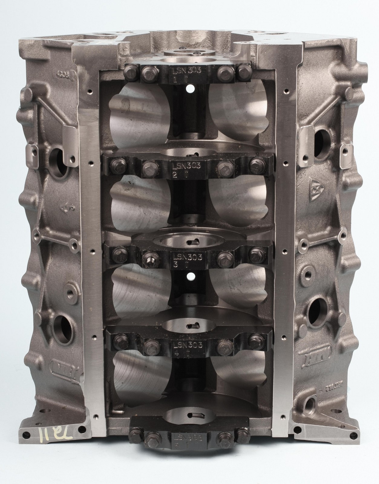


The LS Next Block
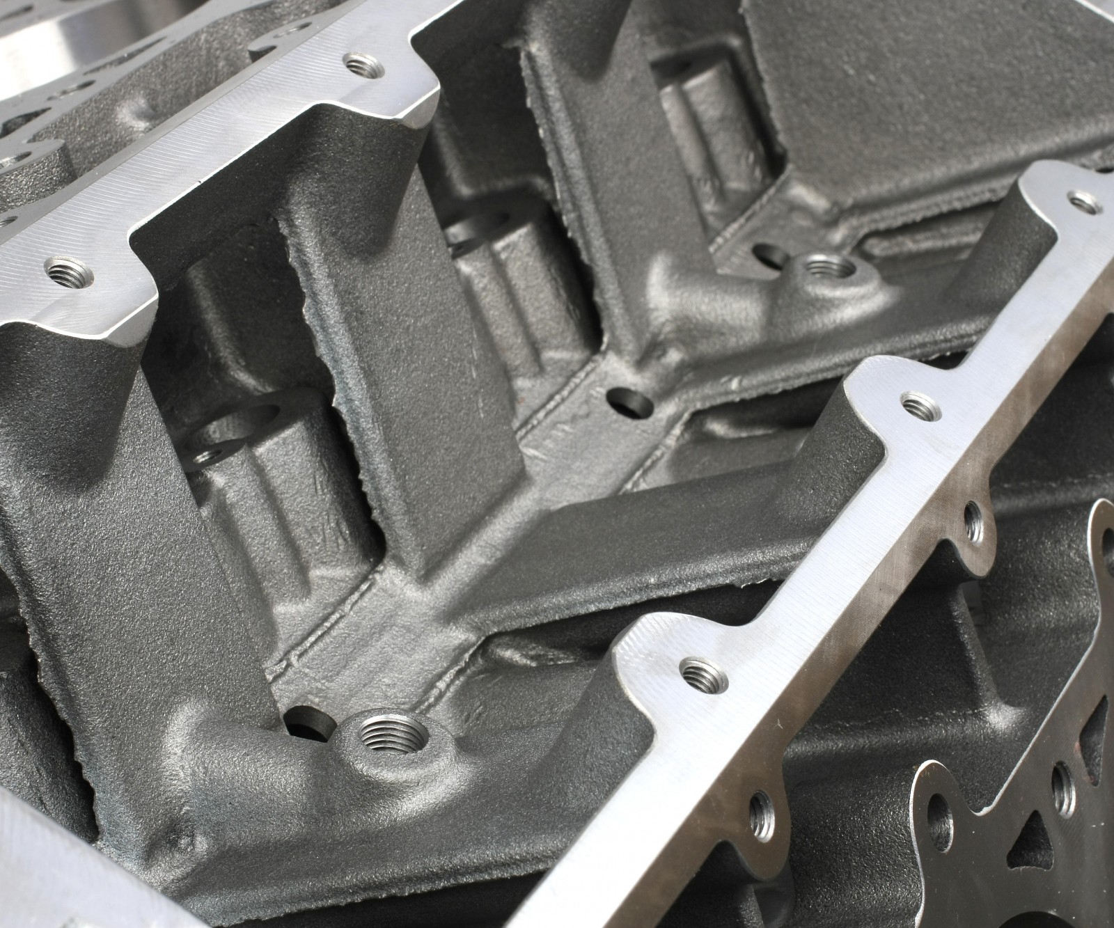
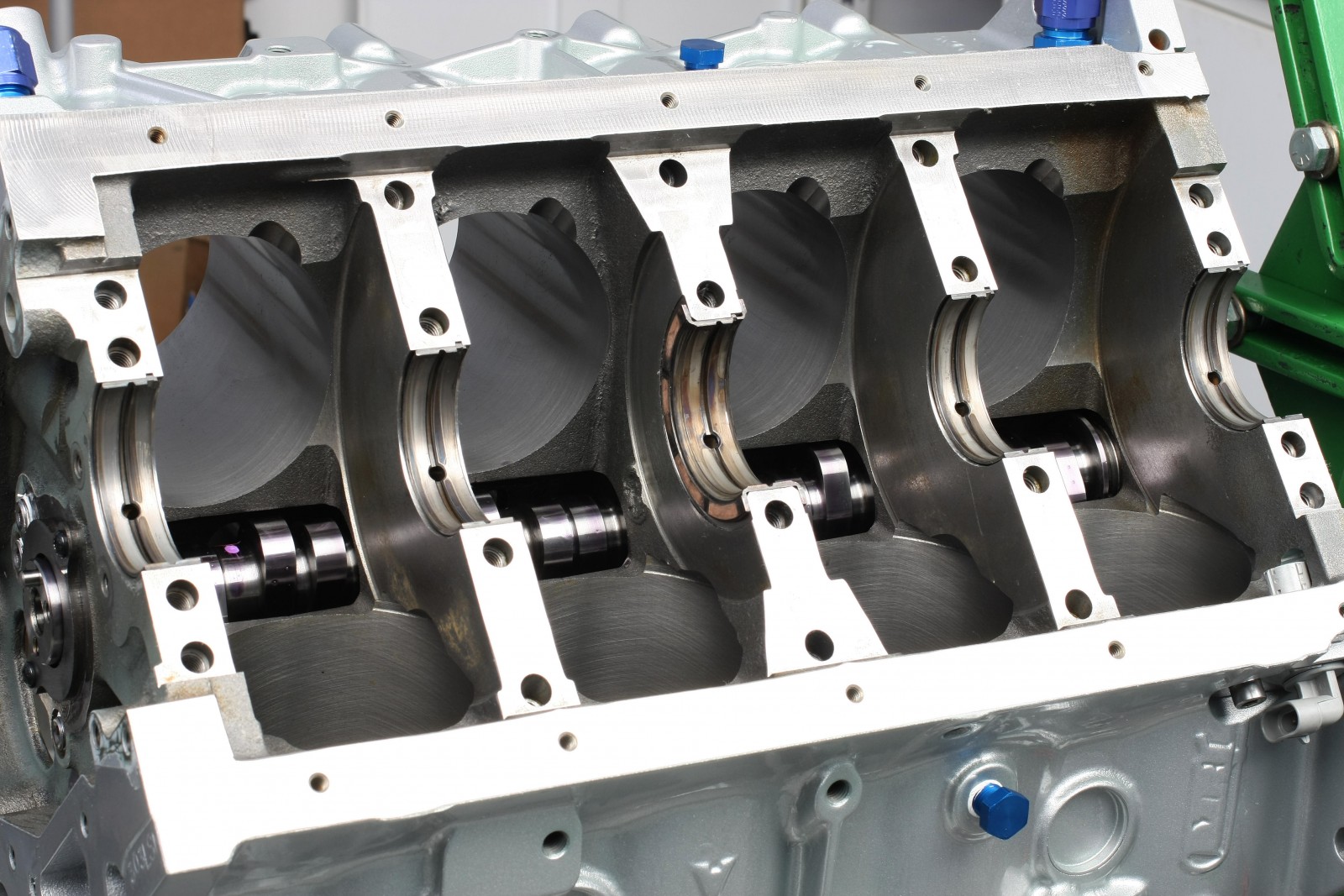
Dart’s LS Next block has numerous improvements that eliminate some of the weaknesses and compromises of factory LS blocks. The biggest change is the elimination of the factory Y-block design with the extended oil pan rails and separate crankcase bays. The crankcase is more like a traditional small block Chevy, so the block is stronger and windage is reduced. The block requires a special oil pan; Stef’s, Canton Racing Products, and Moroso make them.
- Other LS Next features include:
- Priority main oiling system (main bearings get oil first, then cam bearings)
- Deck height is 0.002-0.005 inch taller to accommodate additional machining
- 1.5 inch press-in freeze plugs instead of OEM threaded plugs
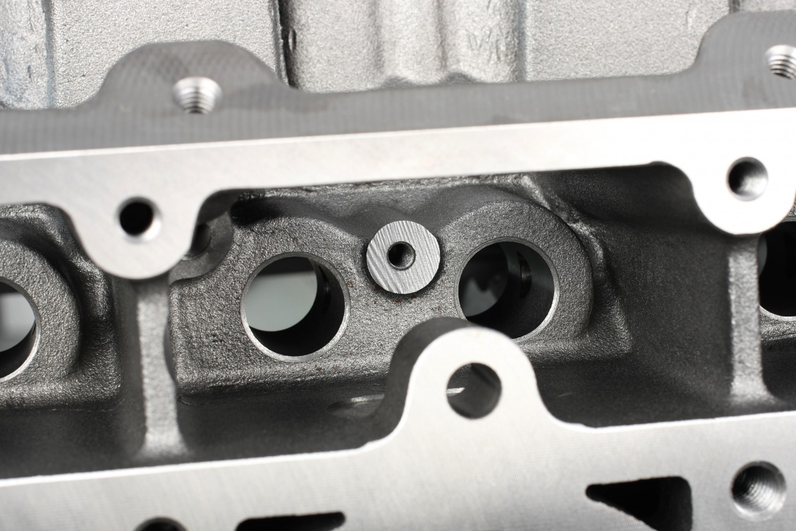
- Accommodations for 23-bolt type cylinder heads
- Accepts a stock style oil pump or external pump
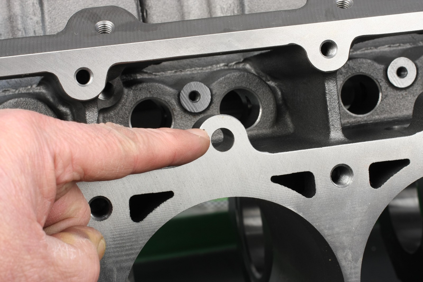
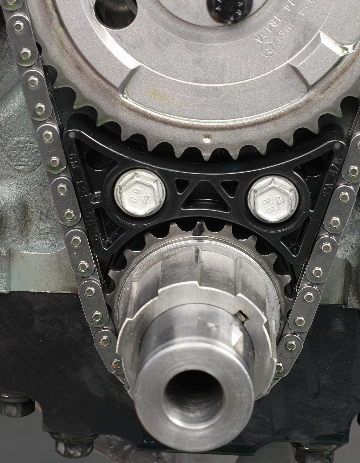
The shorter oil pan rails require the use of a remote oil filter and a factory style Cloyes timing gear. Double row timing chains require block clearancing. The camshaft retaining plate and bolts are unique and supplied with the block.
A Dart block completion kit is a good investment. It includes six 1.5-inch freeze plugs; two bellhousing dowels; four head deck dowel sleeves; two 1/4 inch NPT male hex head plugs for water drains; seven 1/4-inch NPT female hex plugs; and three 1/8-inch NPT female hex plugs.
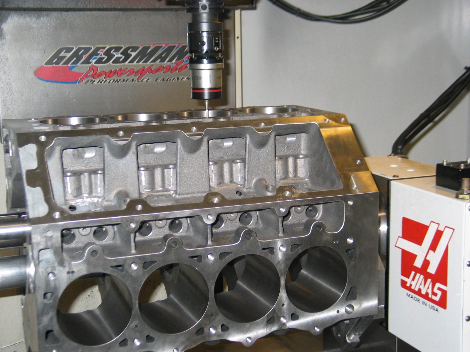
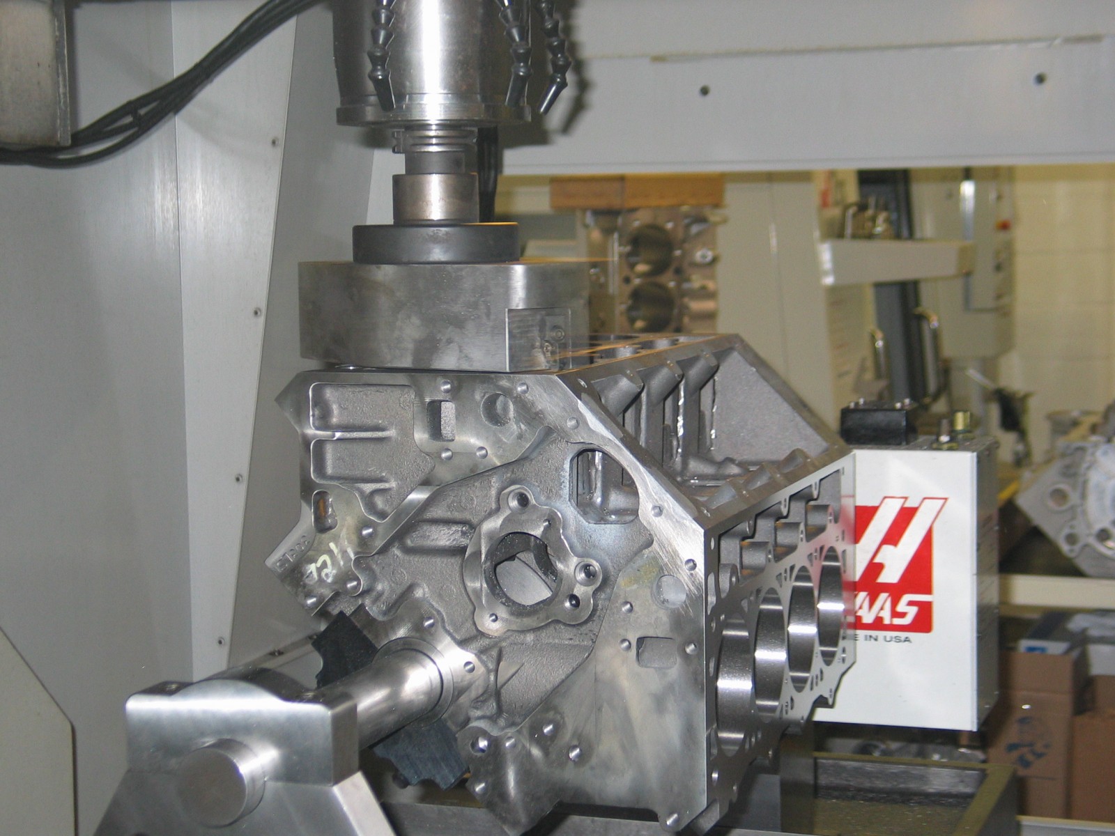
Block Machining
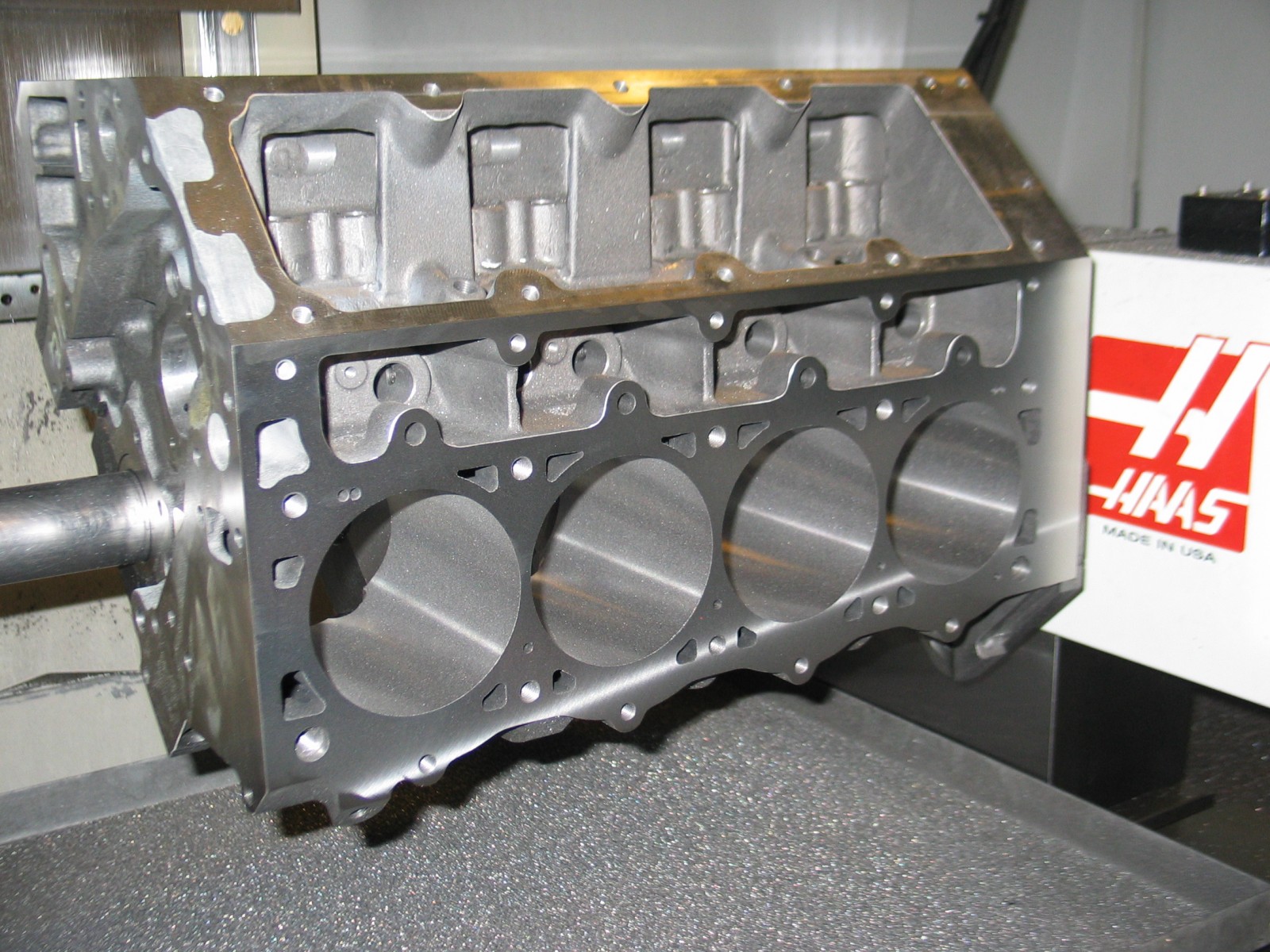
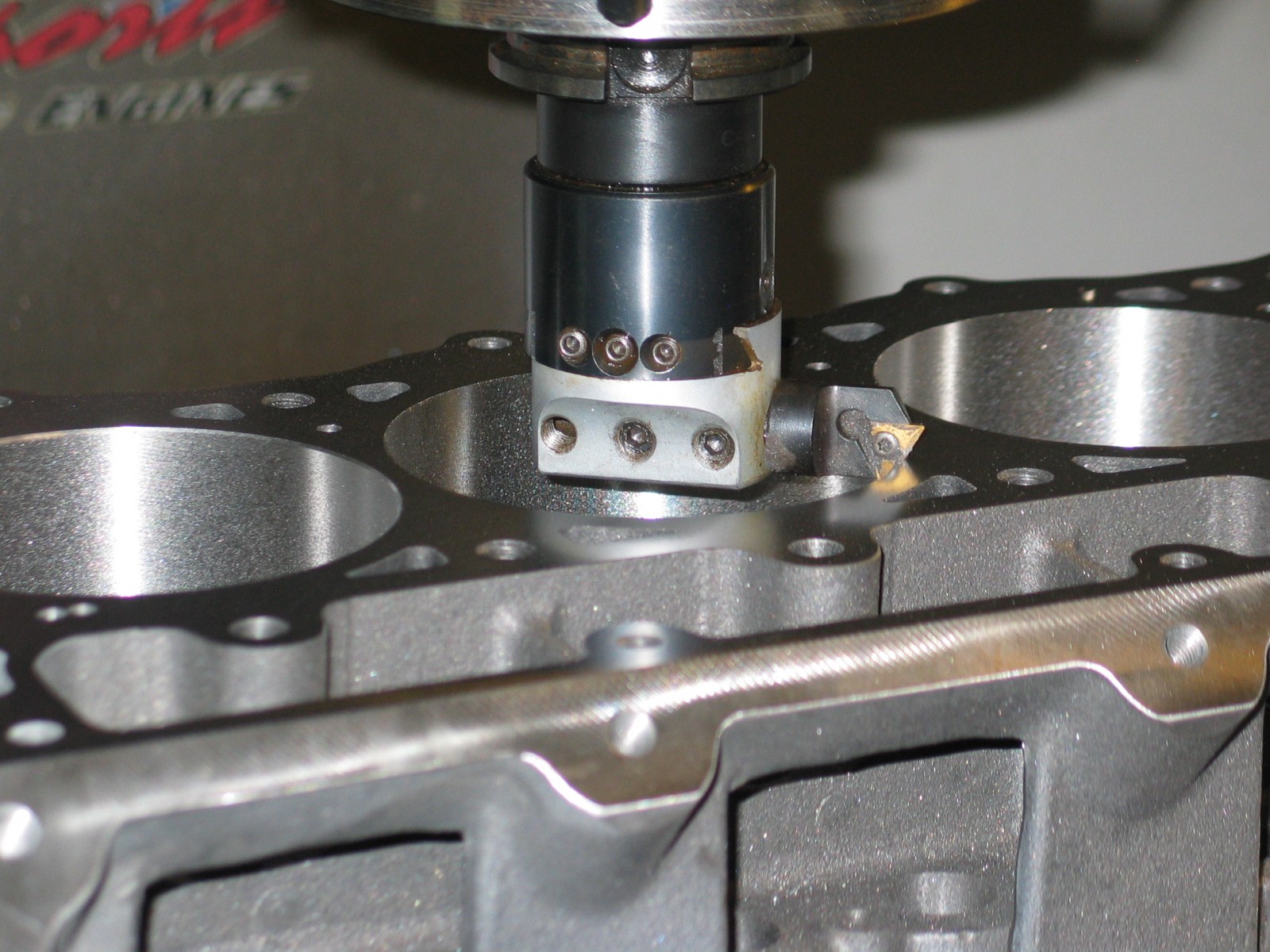
Our block was finish-machined at Gressman Powersports in Fremont, OH. The block was bored, decked, and squared on a CNC block machining center. Cylinders were bored from 4.125 to 4.180 inches in two steps, leaving 0.005-inch for final honing. Deck height came in at 9.2370 inches.
The block was final-honed using torque plates and the ARP head studs that will be used during final assembly. The finished 4.185-inch bore diameter accommodated the required 0.0055-inch piston-to-wall clearance for our JE pistons. The main bearing bores were checked for size and alignment, but Dart did such a nice job that no additional honing was necessary.
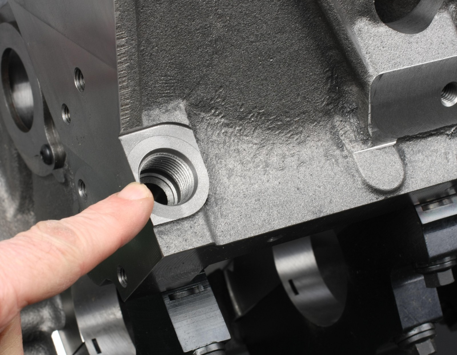
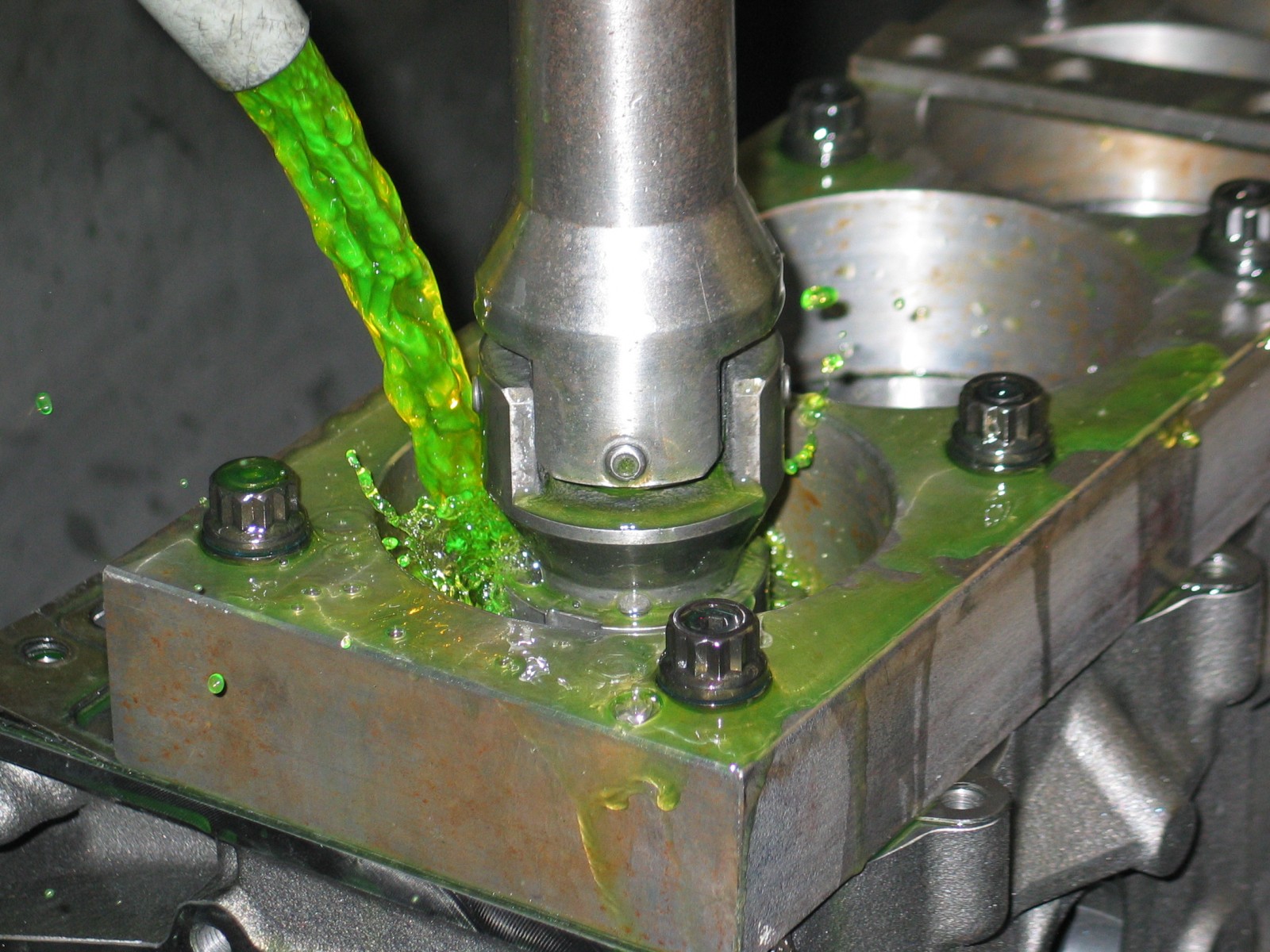
Threaded holes should be checked on any new block. It’s common for threaded holes to have the threads cut too short. During pre-fitting of various components, we tapped the 8mm x 1.25 holes for the oil pump and front cover fasteners about 5mm deeper. All NPT holes (especially at the rear of the block) were tapped a bit deeper as well in order to prevent the plugs from interfering with the rear engine cover.
We completely deburred the block and sprayed it with heavy-build urethane primer. The primer was sanded smooth before spraying the block Valspar Silver Sunshades, an aluminum/silver color. Once the basecoat dried, two coats of urethane clearcoat were applied.
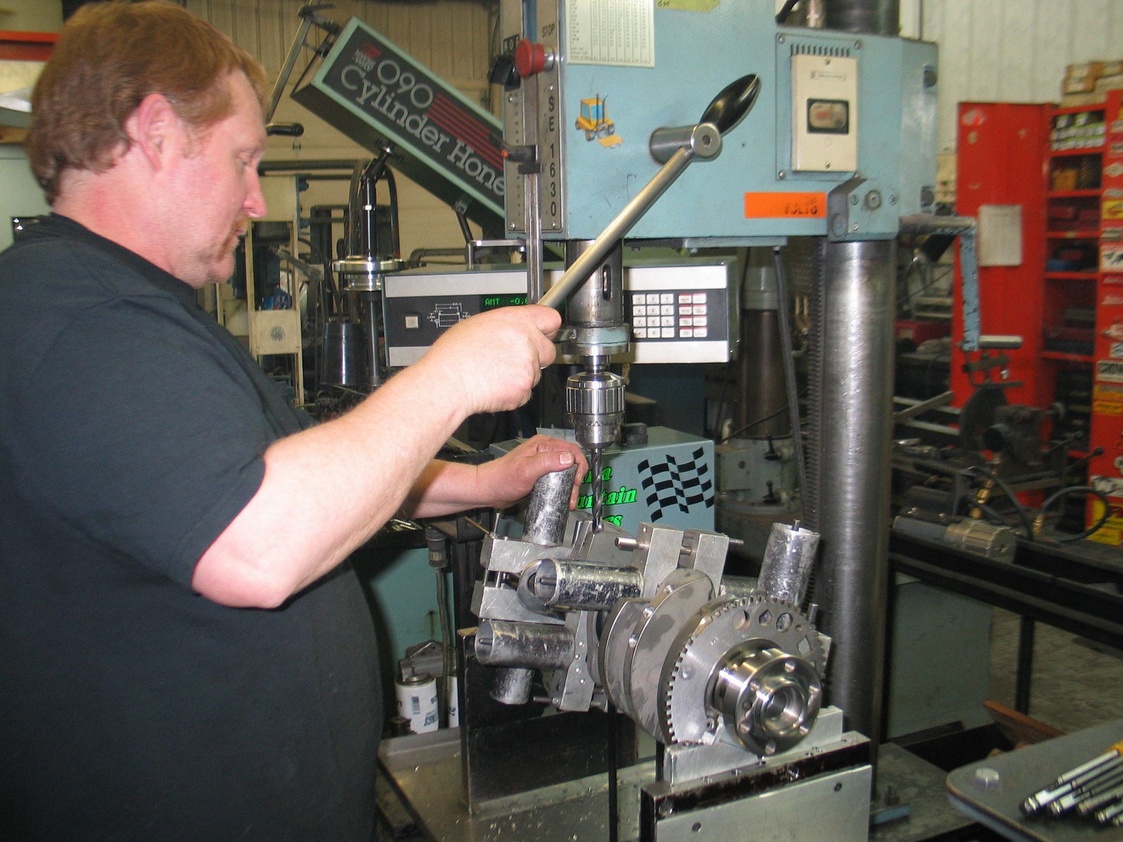
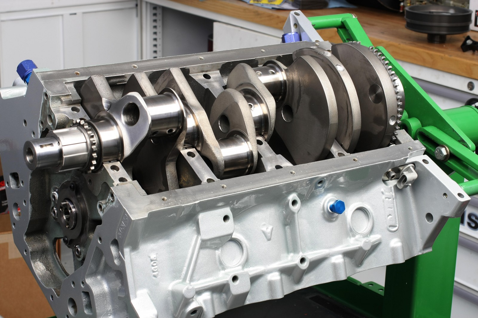
Crankshaft Balancing
The Scat forged crankshaft was precision balanced at Medina Mountain Motors in Creston, OH. Bobweights were assembled once pistons, connecting rod big and small ends, rod bearings, rings, wrist pins, and pin locks were weighed. The crank was internally balanced to within 0.2 grams. Balancing was achieved by removing a total of 18.125 grams from the front and rear counterweights—no heavy metal was needed.
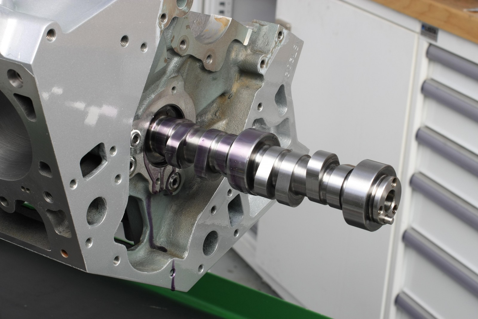
Camshaft
We chose a COMP Cams hydraulic roller camshaft for this engine. Specifications are:
- Gross valve lift: 0.624-inch with 1.7:1 ratio rockers
- Advertised Duration: 292-degree intake/300-degree exhaust
- Duration @ 0.050-inch: 243-degree intake/ 251-degree exhaust
- Lobe separation: 114 degrees
- Intake valve timing @ 0.006-inch: 34-degree open BTDC/78-degree closed ABDC
- Exhaust valve timing @ 0.006-inch: 86-degree open BBDC/ 34-degree closed ATDC
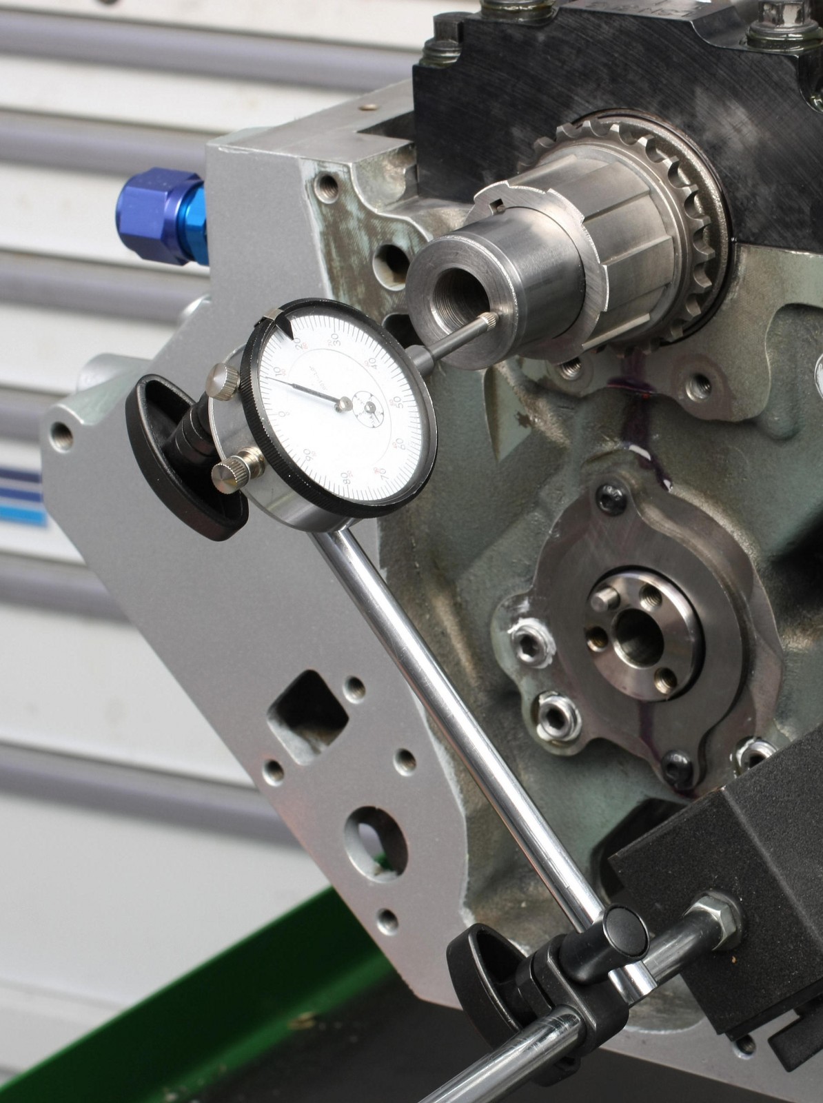
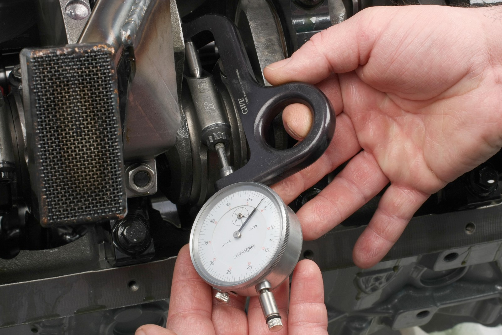
Recommended endplay is 0.005-0.010-inch; ours measured 0.006-inch.
Crankshaft Installation
Dart obviously had stroker cranks in mind when they designed the block—there were no clearance issues whatsoever when we checked counterweight to block clearance. Main bearing clearance measured 0.00188-0.00190-inch. Crank endplay was 0.0075-inch.
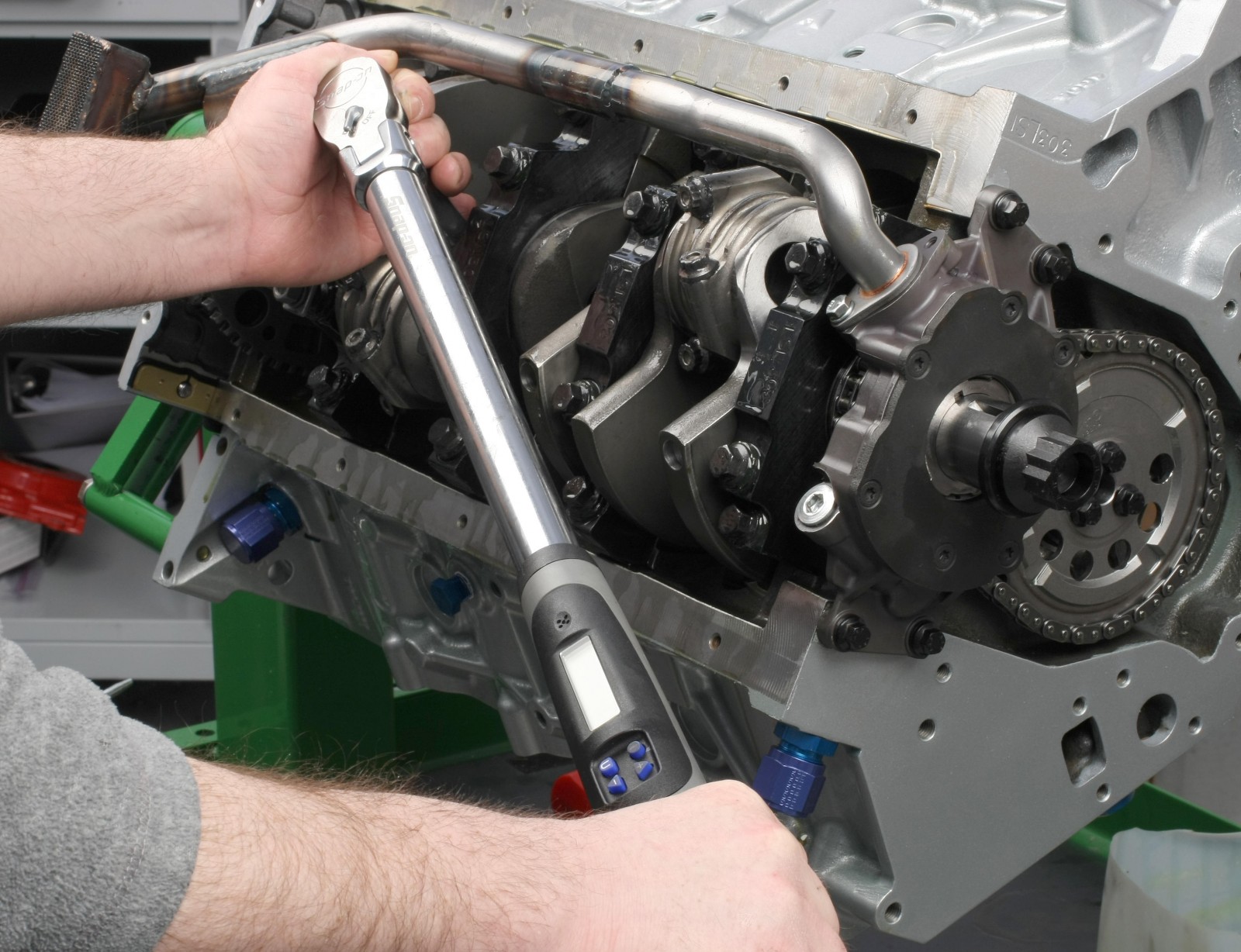
During final installation, the 7/16-inch main cap bolts were snugged to 65 ft.-lbs in three stages: 30 ft.-lbs, 45 ft.-lbs, and 65 ft.-lbs. Crank rotation was checked after each stage—we could rotate the crank with two fingers on the snout. The Mahle/Clevite main bearings were coated with Royal Purple Max-Tuff assembly lube.
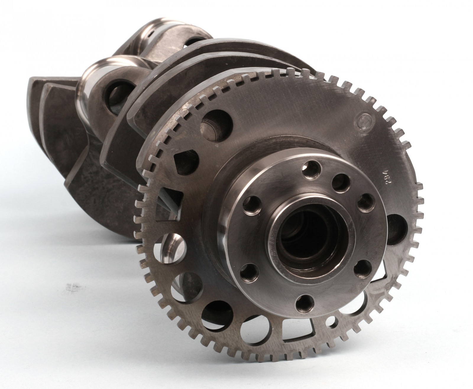
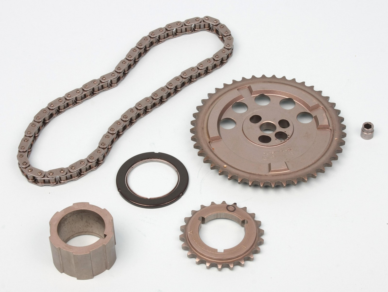
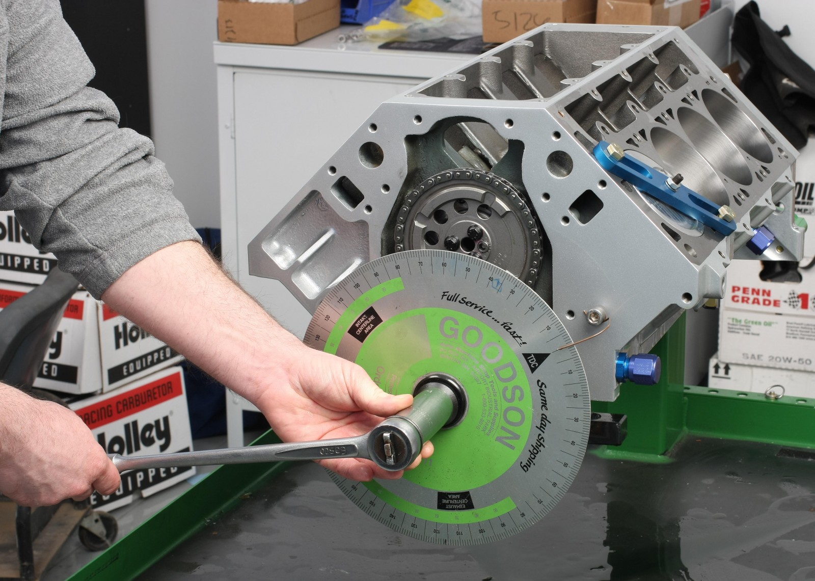
Timing Set
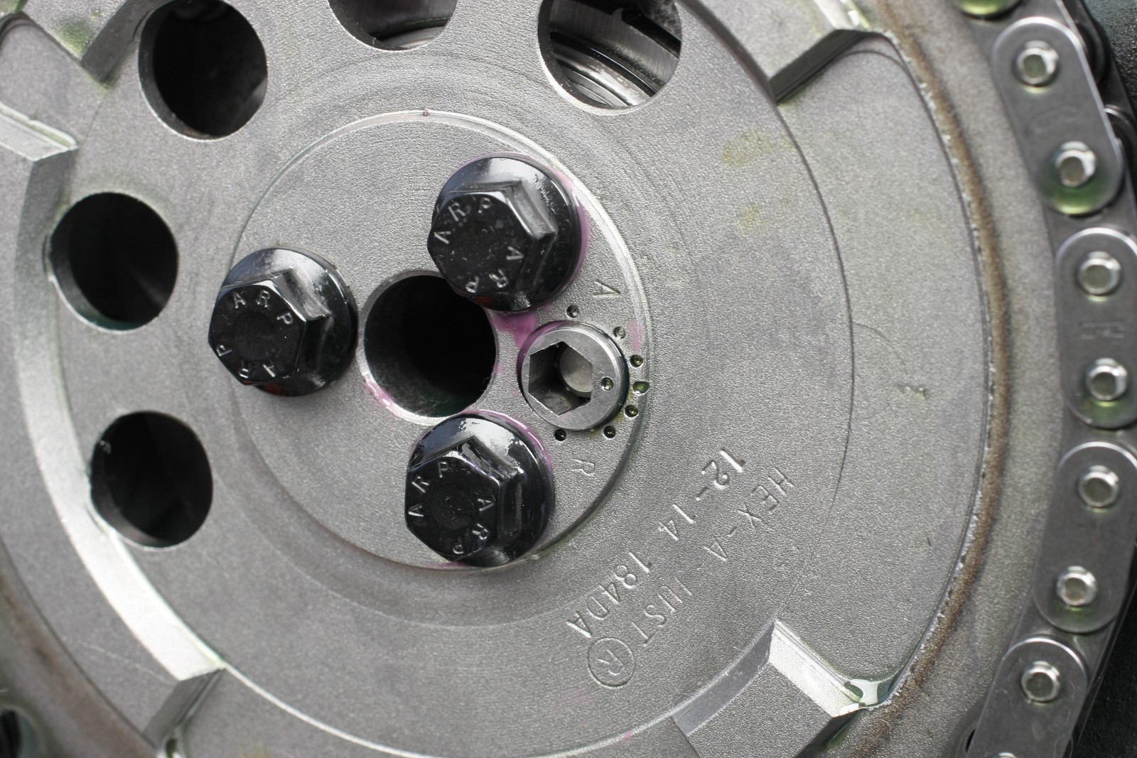
After installing a key in the crank snout’s rear (long) keyway, the Cloyes crank gear was tapped into place. The “standard” timing slot was engaged to the key (the rounded slot). This places the zero timing mark counterclockwise relative to the key. The oil pump drive gear was installed on the same key.
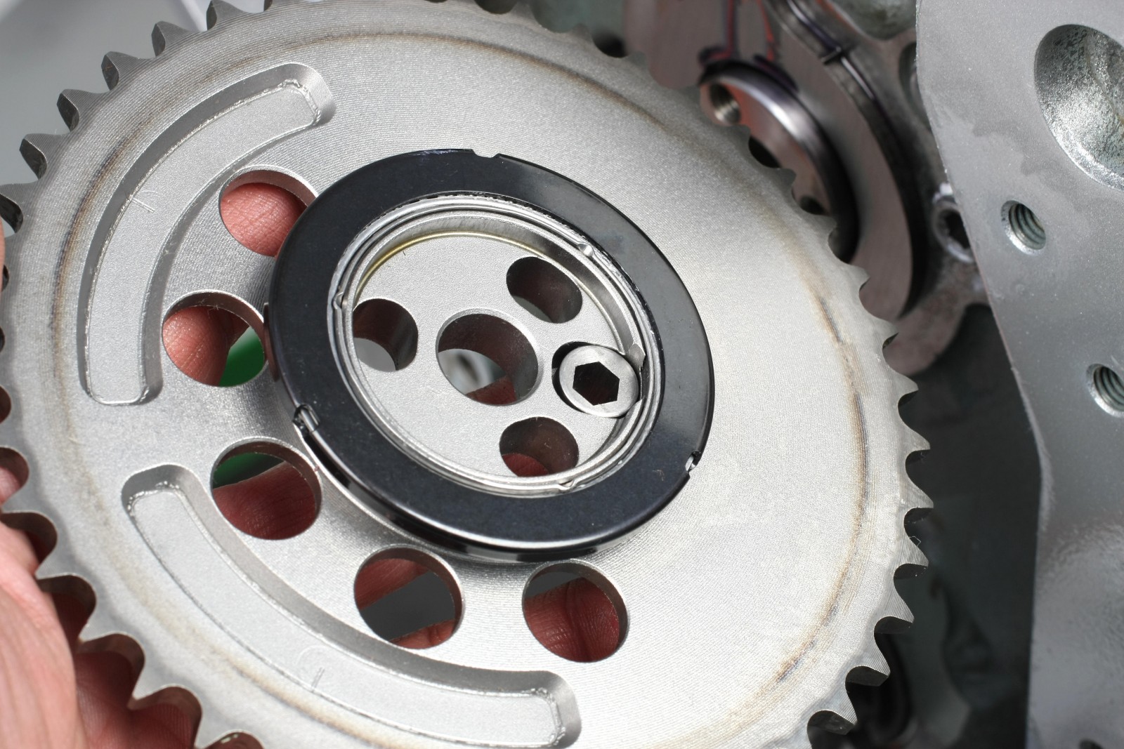
The cam gear features a Torrington bearing that installs at the rear of the gear. The black side of the bearing must face the engine block. The eccentric cam timing button fits in the cam gear’s drive pin hole. The rear of the button engages the camshaft’s dowel pin. The eccentric button is adjustable so you can fine-tune cam timing during cam degreeing.
After soaking the timing chain in 30W engine oil overnight, we installed the cam gear and chain and tightened the ARP cam gear bolts to 25 ft.-lbs. A dab of Loctite 242 helps secure the bolts.
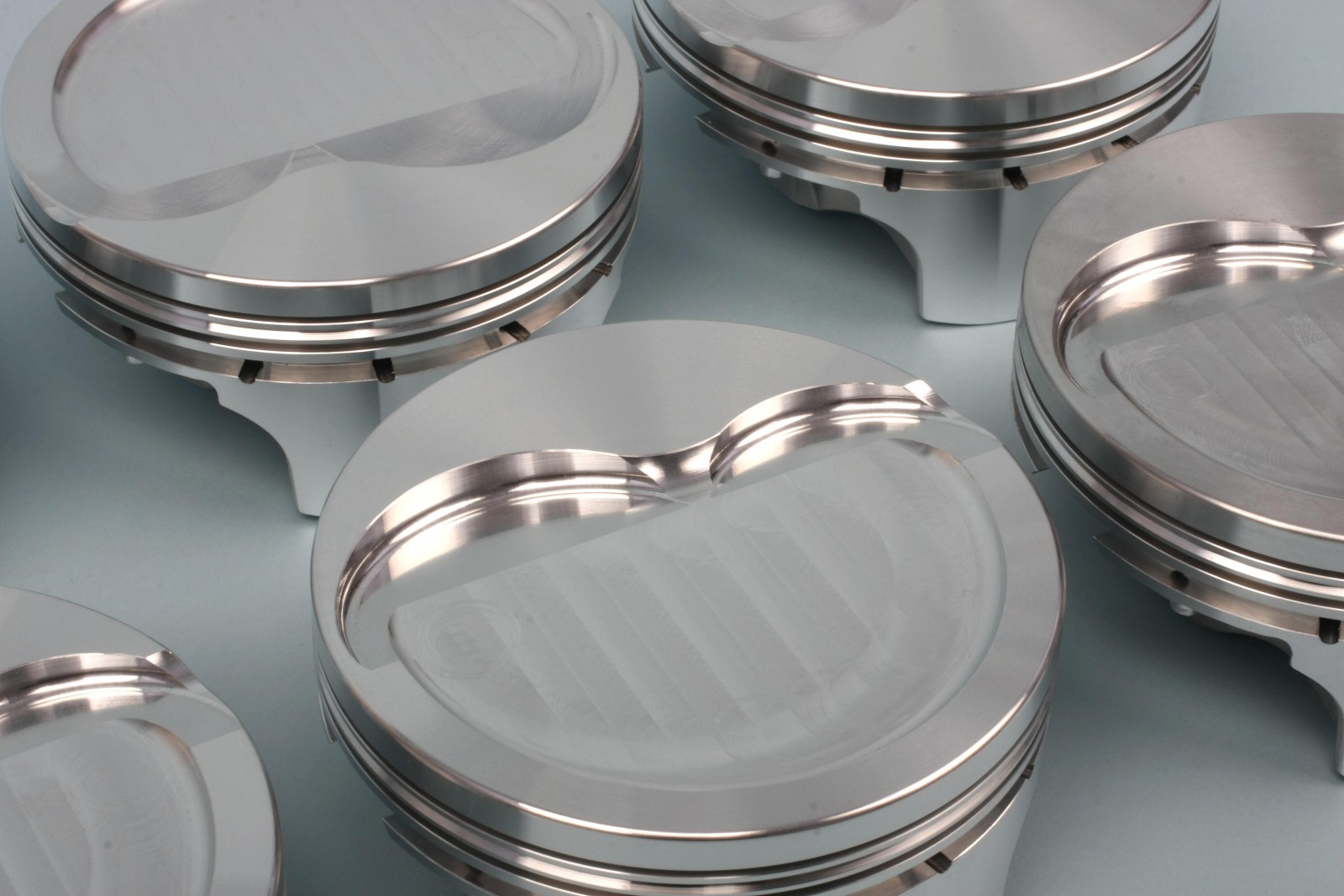
Pistons
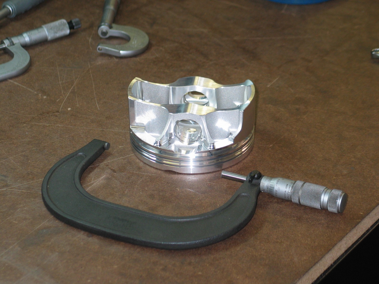
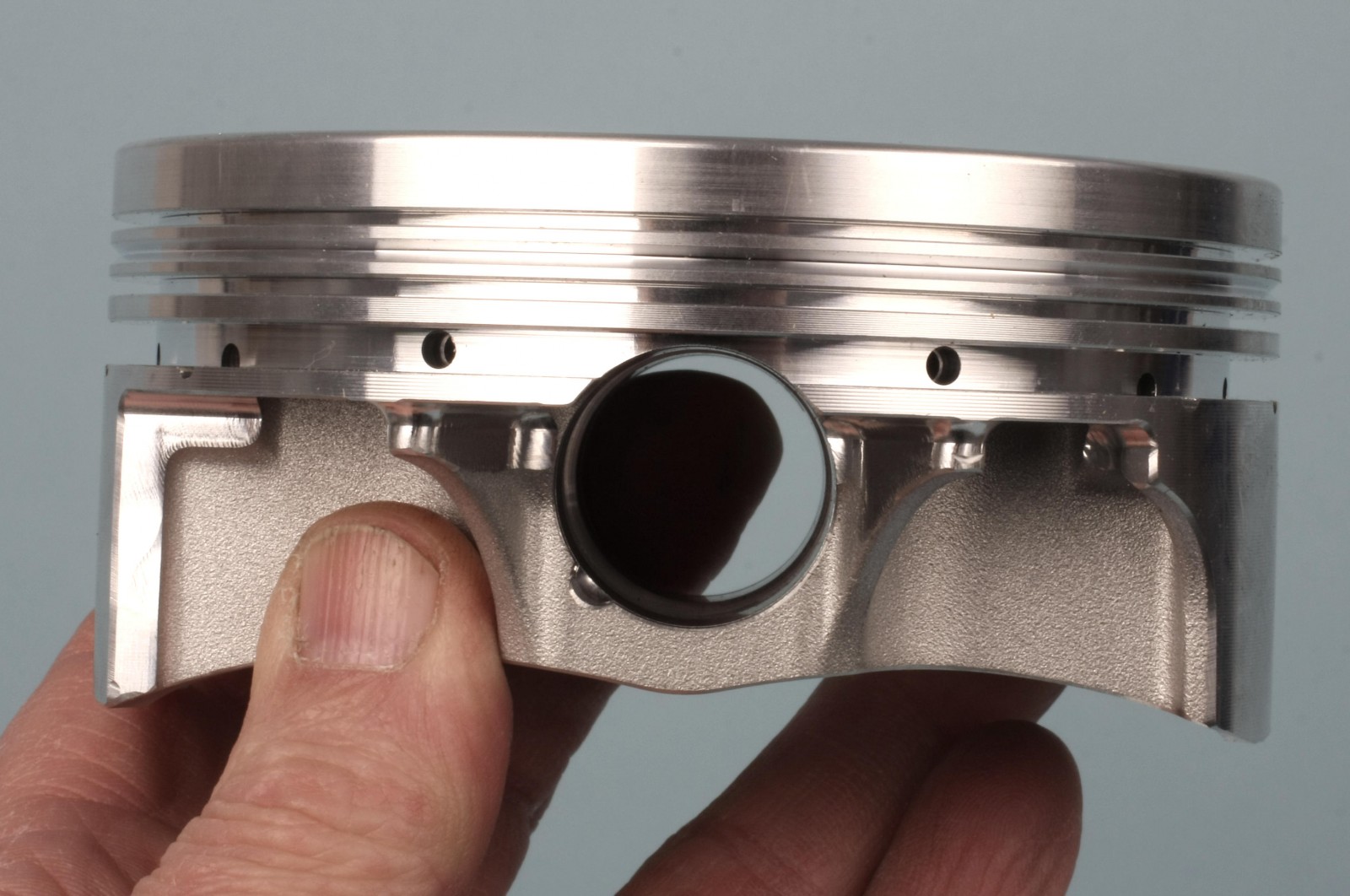
Our JE pistons feature an asymmetric design. The thrust side has a conventional-width skirt, while the unloaded side skirt is narrower. This saves weight while adequately supporting the thrust side of the piston. To give you an idea of the difference in skirt width, our piston skirts are approximately 2.030 inches wide on the thrust side and approximately 1.460 inches on the non-thrust side, as measured from the bottom of the skirts. The thrust sides face the outboard side of the right bank cylinders and the inboard side of the left bank cylinders.
Since the on-center balance weight of the piston (relative to the wrist pin bore centerline) is altered, the pin bore centerline was moved about 0.020-inch toward the piston’s thrust side to compensate.
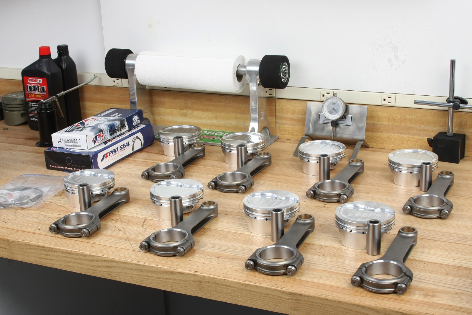
Piston/Rod Assembly
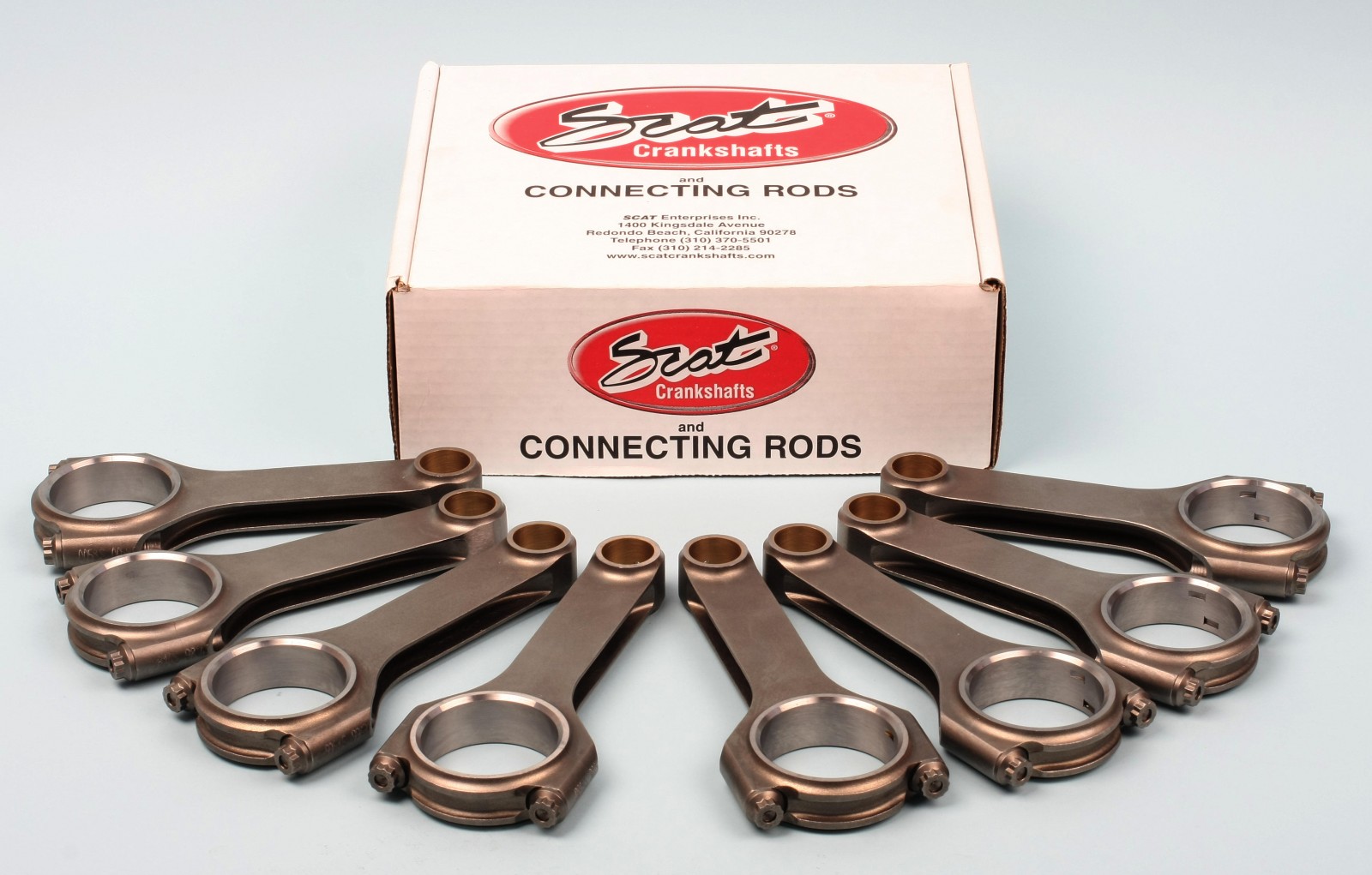
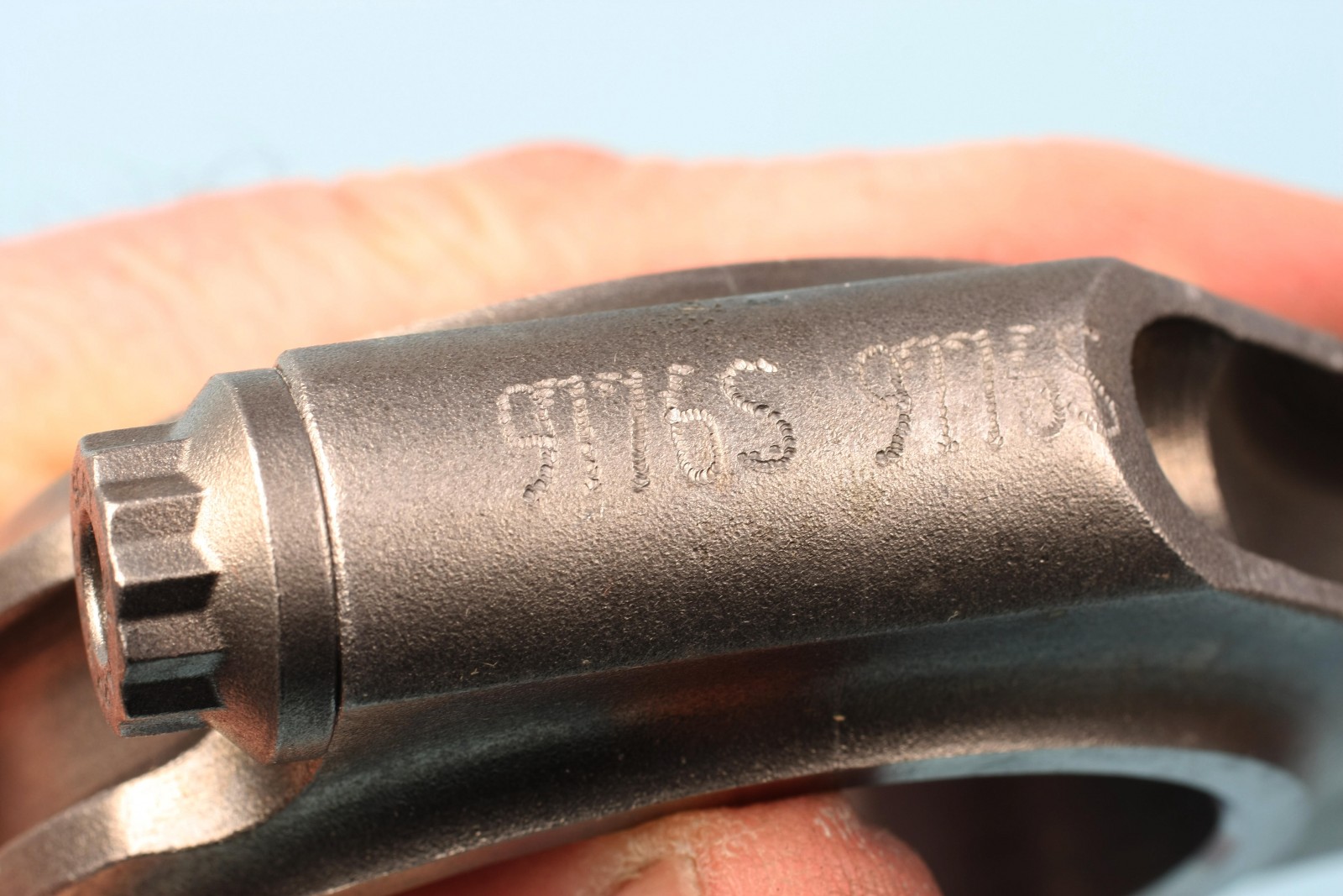
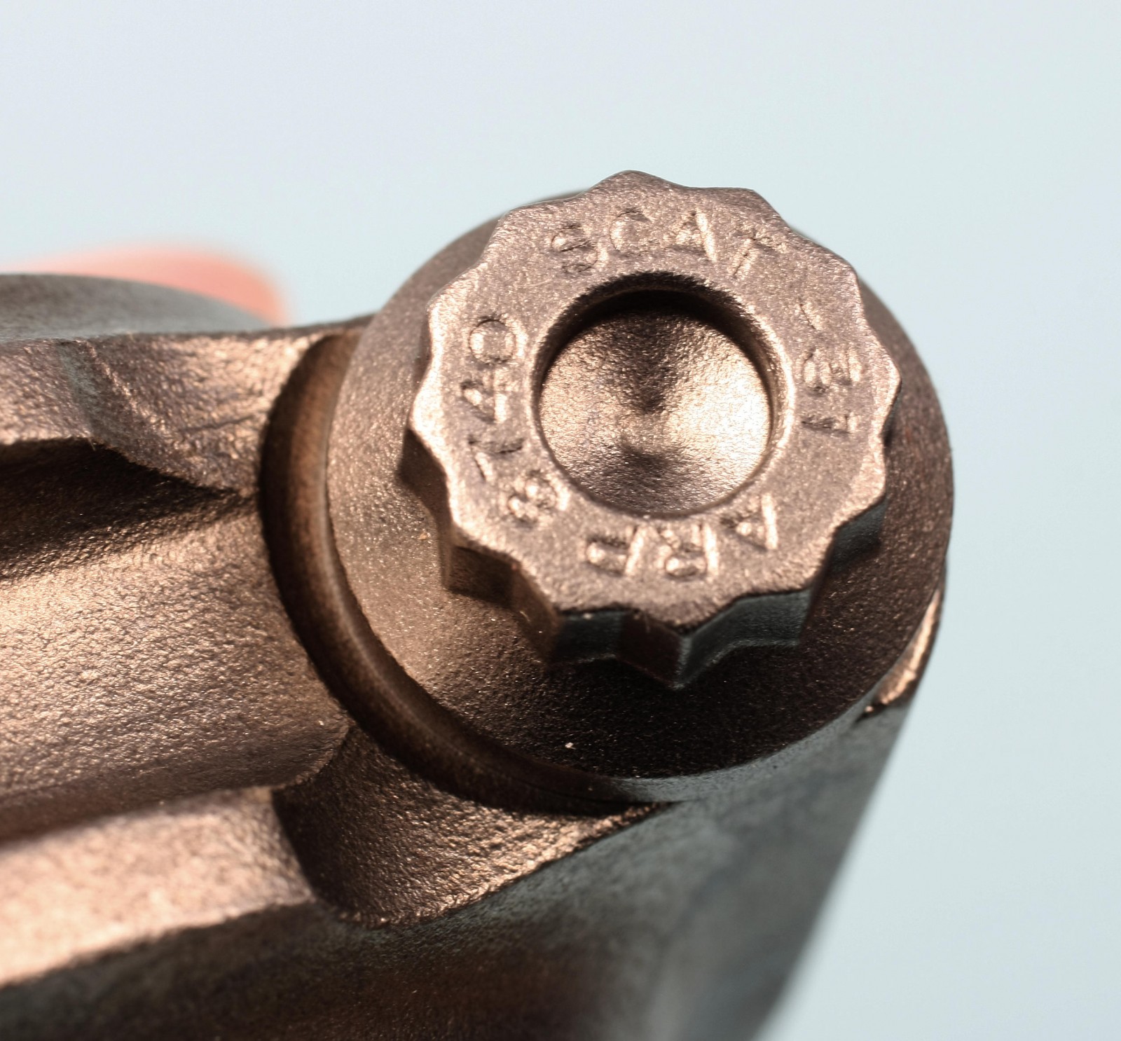
Our Scat forged 4340 steel rods are an H-beam design with doweled caps, and are profile clearanced for stroker applications. The rods feature a center-to-center length of 6.125-inch and are fitted with ARP 8740 12-point bolts.
Since the pistons are asymmetrical and are cylinder bank-specific, each piston dome is lightly stamped by JE with a “FRONT” designation and an arrow symbol. When installing pistons on the connecting rods, the larger chamfer on one side of the rod big ends must face forward on the left cylinder bank and rearward on the right bank.
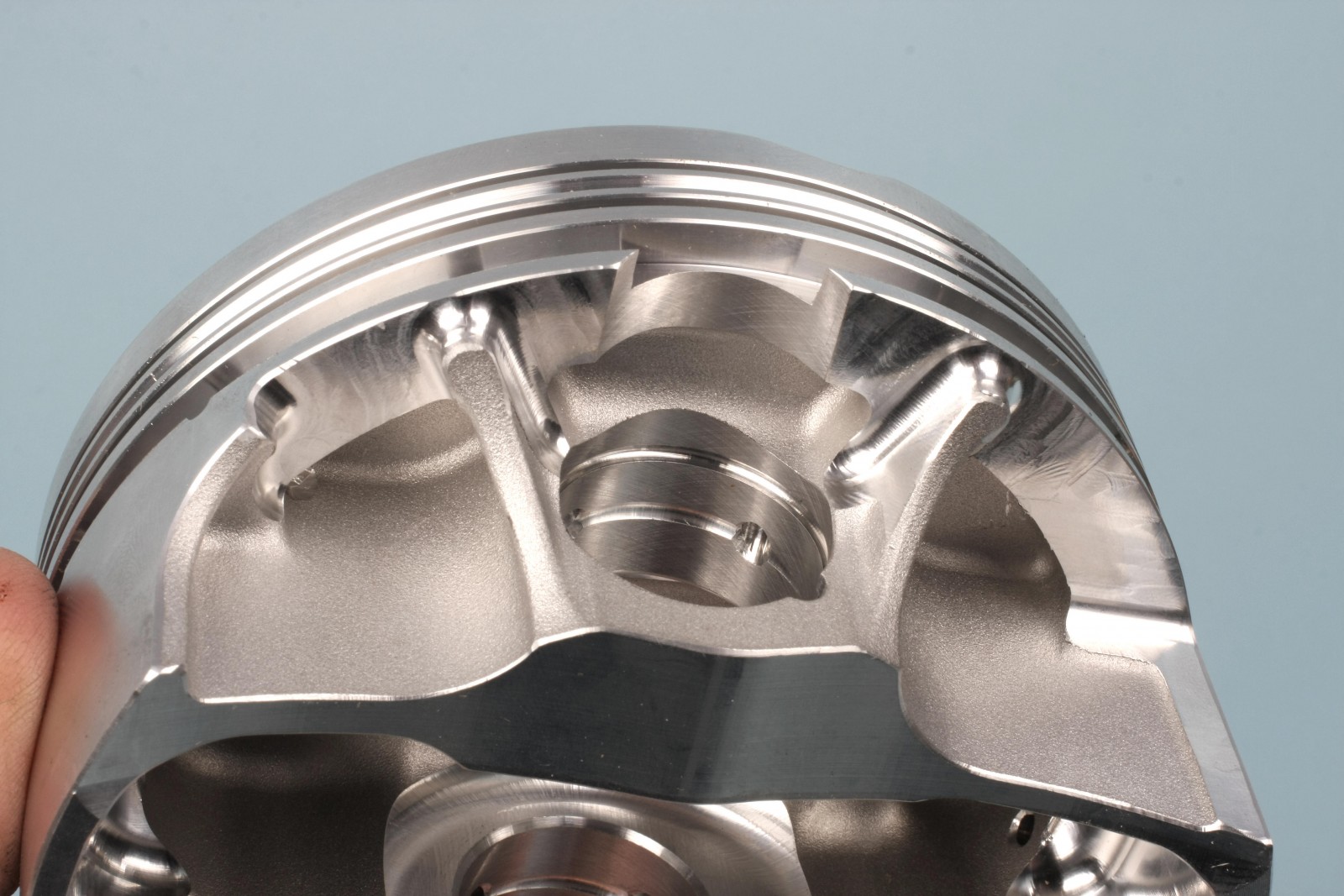
Piston Rings
The pistons came with a ring set and support rails that install on the bottom of the oil ring land. The pistons’ short compression height means the wrist pin bore slightly intersects the oil ring groove. The rails are needed to provide oil ring support at the outside of each pin bore end. Install each support rail so that the small male dimple aligns at the center of the pin bore area and faces downward. This dimple serves as a stopper to prevent the rail from walking and keeps the rail’s gap well away from the open pin bore cutouts.
The top and secondary rings required file fitting. JE recommends ring end gaps of bore size x 0.0045-inch for top rings and bore size x 0.0050 inch for the secondary rings. We used a Summit Racing bench-mounted ring filer to create a 0.019-inch gap for the top rings and a 0.021 inch gap for the secondary rings.
Even though the cylinders were CNC machined and accurately honed to size, we file fit each top and second ring on a per-cylinder basis, keeping them organized for each individual cylinder. This probably isn’t necessary, but it allows you to verify proper ring gap for each cylinder.
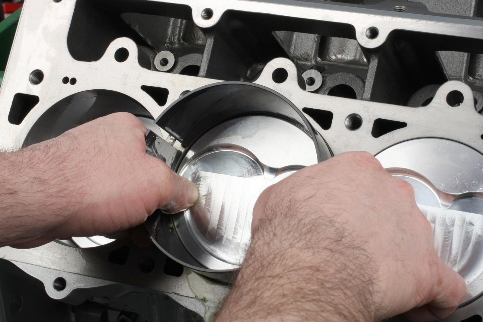
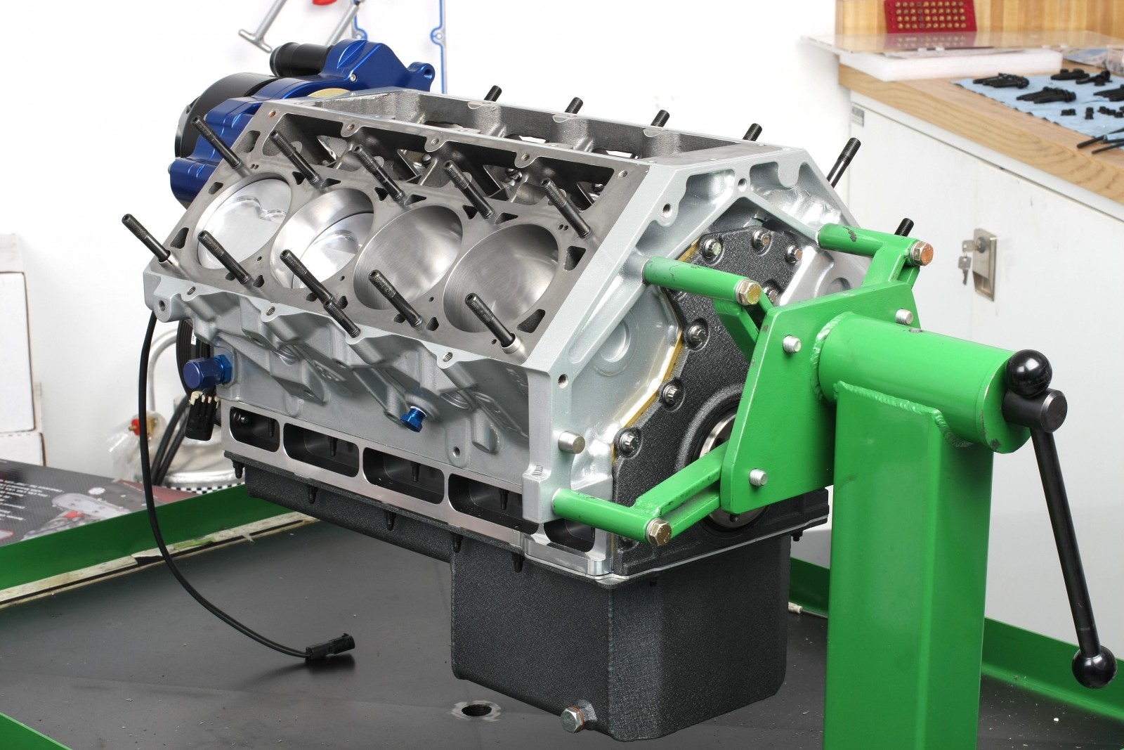
Piston/Rod Assembly Installation
We installed the rods and pistons using an adjustable Summit Racing piston ring compressor. It features a split design so the tool can be adjusted for bore diameters from 4.120 to 4.220-inch. A tapered inner wall smoothly compresses the ring package as the piston slides into the cylinder bore. We used a plastic piston hammer with an extended snout to gently tap each piston down while aligning the rod’s big end onto the crank journal.
The Dart LS Next block has notches at the bottom of the bores for rod bolt clearance. Our closest rod bolt head to block clearance was approximately 0.300-inch, so no additional block notching was required.
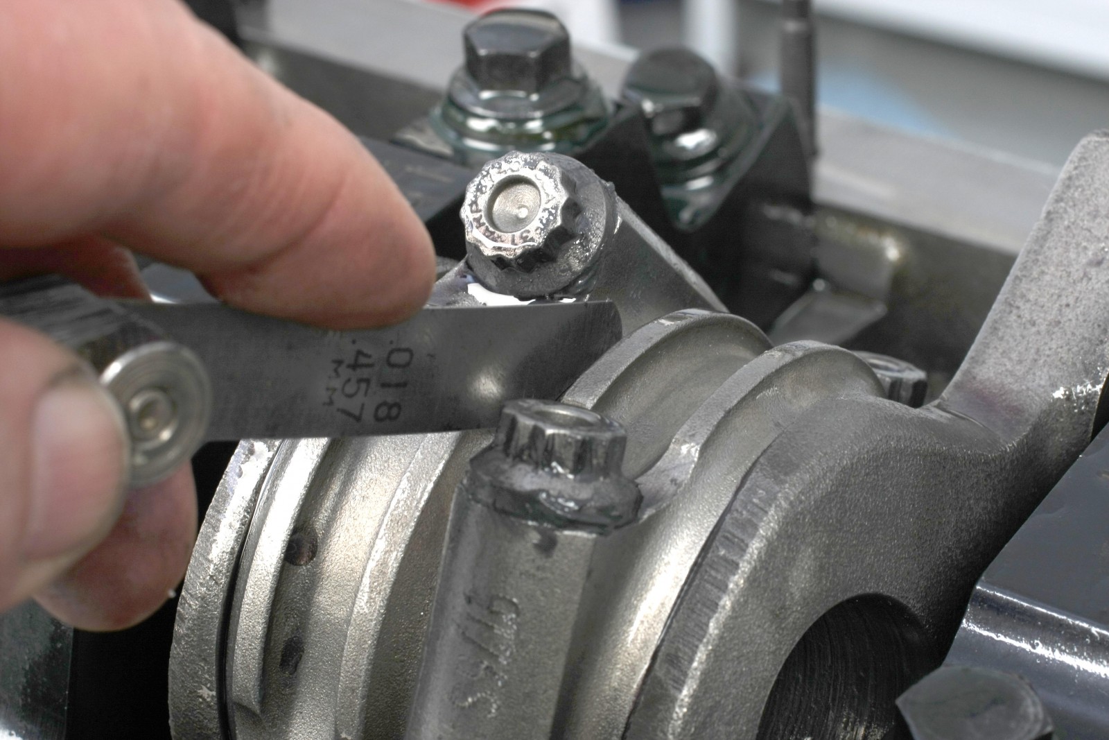
Scat recommends the rod bolts be torqued to 64 ft.-lbs using ARP moly lube. Bolt stretch is not to exceed 0.0046-inch. We used a rod bolt stretch gauge to check this. With each bolt torqued to spec, rod bolt stretch measured between 0.0035 and 0.004-inch.
We achieved the desired 0.002-inch rod bearing oil clearance by using Clevite HNK upper bearings and Clevite HXNK lower bearings. Rod sideplay measured 0.0018 to 0.0019-inch at all big end locations.
In Part Two of the LS Next 440 build, we’ll dive into the oiling system, cylinder heads, and valvetrain.
Why are the bearing clearances so tight? Under 002 on the mains and just 002 on the rods? way to tight for a engine like this. And rod side clearance under 002?? are these misprints?
I purchased this motor from Mike.
His paper work that came with motor says:
“Advise using 5W-40 oil (required for Morel lifters)”
According to the builder, bearing clearances were set for use with 0W-40 or 5W40 oil. Rod side clearance is 0.018-0.019”
[…] Part One, we covered the block prep, the rotating assembly, and camshaft installation. This round is devoted […]
Wondered what ever happened to you after the race Retread Challenge I was on your pit crew as the jack man What ever happened to Steve Walker